Decorative lighting string with stacked rectification

a technology of led light strings and rectification, which is applied in the direction of lighting elements, display means, lighting and heating equipment, etc., can solve the problems of reducing the appearance of the led light string, adding cost, and potential safety hazards

Active Publication Date: 2007-10-02
FIBER OPTIC DESIGNS
View PDF89 Cites 64 Cited by
  • Summary
  • Abstract
  • Description
  • Claims
  • Application Information

AI Technical Summary

Benefits of technology

[0008]In view of the disadvantages of the prior art, the object of the present invention is to provide an improved decorative light string circuit that can solve the problems mentioned previously.
[0009]To attain the aforesaid object, the present invention comprises full bridge rectification located in or downstream of the front plug, said rectification circuit containing one or more voltage reducing and / or filtering elements in order to reduce or limit LED drive current and reduce (filter) DC ripple and 1 or 2 LED series sets. Additional rectification circuits and LED series sets can be added in parallel to the first in “stacked mode”, with each rectification circuit and LED series set electrically independent of prior and subsequent circuits. This eliminates the rectifying diode current summation load restrictions imposed by prior art and associated safety hazard due to diode overheating.
[0010]Another advantage of the present invention is nearly unlimited design flexibility whereas prior art has significant limitations. For example a light string can be manufactured without a cord connector using only 2 wires, eliminating the third conductor wire and dummy plug requirement of the prior art shown in FIG. 2. A light string with a cord connector can be manufactured with one or two blocks of series connected LED lamps without adding components, or can be manufactured as a continuous roll with a nearly unlimited number of parallel connections, with or without a cord connector that is simply cut to the desired length according to the stacking aspect of the invention. A continuous roll of lighting string can therefore be manufactured limited only by the allowable Wattage rating of conductor wire or fuses.
[0013]Manufacturing cost is significantly reduced as the number of conductor wires does not increase as the number of LED series blocks connected in parallel increases. The prior art shown in FIG. 1 requires 5 conductor wires when multiple series blocks of LED lamps are connected in parallel. Prior art shown in FIG. 2 requires 1 additional conductor wire for each parallel connected series block of LED lamps. The present invention requires as few as 2 or 3 conductor wires regardless of the number of parallel connections employed.
[0014]Manufacturing is greatly simplified and made more efficient as the same electrical circuit is used repeatedly. This allows mass production of common electrical components.

Problems solved by technology

However, prior art discloses the use of a full bridge rectification circuit that requires additional wires and / or places undue current load on rectifying diodes, detracting from the appearance of the light string and creating a potential safety hazard.
The invention disclosed defeats the wire saving purpose, adds cost, places severe limitations on the design, and complicates the manufacturing process.
Both of the light string designs shown in FIG. 1 and FIGS. 2A and 2B create a safety hazard when additional series blocks of LED lamps are employed.
The AC to DC converter (rectifying diodes) will quickly overheat due to the increased electrical load (current summation) imposed by the additional parallel connected series blocks of LED lamps.
Accordingly, both of these designs have severe limitations.

Method used


Image

  • Decorative lighting string with stacked rectification
  • Decorative lighting string with stacked rectification
  • Decorative lighting string with stacked rectification

Examples


Embodiment Construction

[0026]Reference will now be made to the exemplary embodiments illustrated in the drawings, and specific language will be used herein to describe the same.

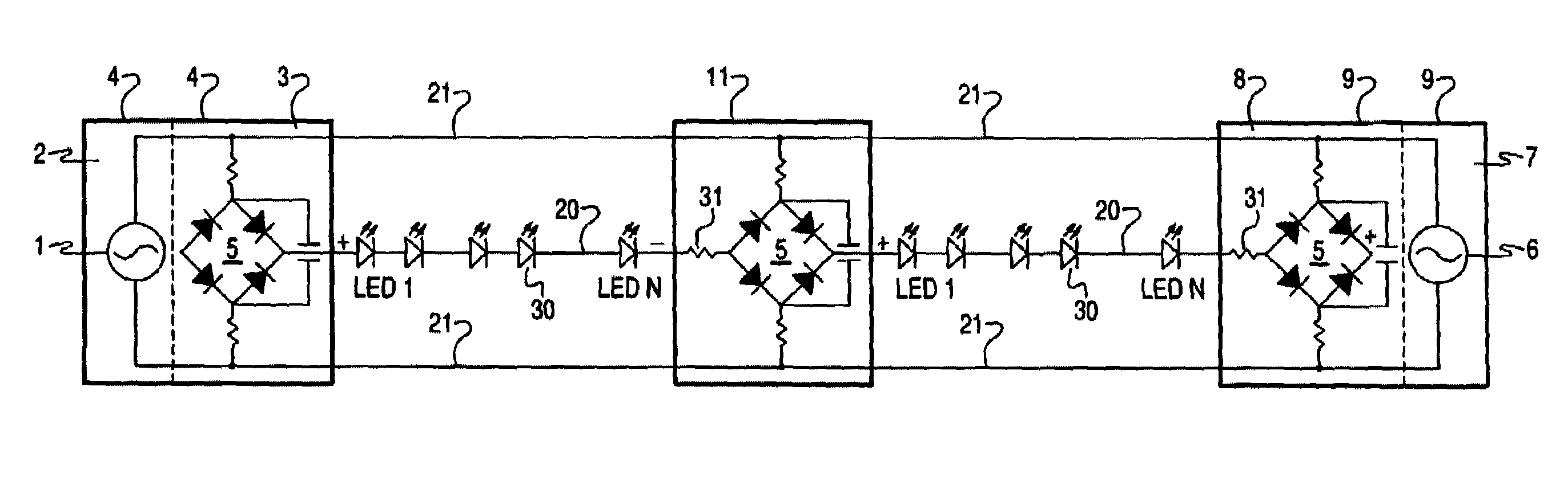
[0027]As shown in FIGS. 4A-4C, the LED light string includes a common household AC input voltage source (01), AC plug (02), front rectification and control circuit (03), parallel conductor wires (21), series conductor wires (20), plurality of series connected LED lamps (30), series resistance (31), rear rectification and control circuit (08), end connector plug (07) incorporating exit AC voltage (06) for powering additional light strings.

[0028]Front rectification and control circuit (03) comprises a full bridge rectifier (05) drawing AC input voltage from parallel conductors (21) via one or more optional resistors (2 are shown in all figures) in order to reduce DC output voltage. The positive DC output terminal of rectifier (05) provides positive DC power to series conductor (20) containing a plurality of serially connected LED lam...


PUM


Abstract

An improved decorative light string circuit comprises full bridge rectification located in or downstream of the front plug, wherein the rectification circuit contains one or more voltage reducing and / or filtering elements in order to reduce or limit LED drive current and reduce (filter) DC ripple and 1 or 2 LED series sets. Additional rectification circuits and LED series sets can be added in parallel to the first in “stacked mode”, with each rectification circuit and LED series set electrically independent of prior and subsequent circuits. This eliminates the rectifying diode current summation load restrictions imposed by prior art and associated safety hazard due to diode overheating.

Description

FIELD OF THE INVENTION[0001]The present invention relates to the field of decorative LED light strings and particularly an improved circuit to be used to connect LED light strings having one or more series connection.BACKGROUND[0002]LEDs are becoming increasingly popular as a light source in decorative and Christmas lights due to their reliability, energy savings, longevity, and cool operation. Manufacturers of decorative light strings are constantly working to maximize the brightness and benefits of LEDs as a light source as well as reduce production cost to narrow the gap between traditional, incandescent and LED light string cost.[0003]It is known in the art the use of a DC power supply to power LED lamps maximize LED brightness and longevity. However, prior art discloses the use of a full bridge rectification circuit that requires additional wires and / or places undue current load on rectifying diodes, detracting from the appearance of the light string and creating a potential sa...

Claims


Application Information

Patent Timeline
Patent Type & Authority Patents(United States)
IPC IPC(8): H05B37/00F21V33/00H05B44/00
CPCH05B33/0803H05B33/0809Y10S362/806Y10S362/80Y02B20/348Y02B20/30H05B45/30H05B45/36
Inventor ALLEN, DAVID
Owner FIBER OPTIC DESIGNS
Why Eureka
Try Eureka