
Controlling transient pressure conditions in a wellbore

a transient pressure and wellbore technology, applied in the direction of wellbore/well accessories, sealing/packing, weapons, etc., can solve the problems of inconvenient operation, inconvenient maintenance, and inconvenient maintenance,

Inactive Publication Date: 2007-10-23
SCHLUMBERGER TECH CORP
View PDF46 Cites 49 Cited by
  • Summary
  • Abstract
  • Description
  • Claims
  • Application Information

AI Technical Summary

Problems solved by technology

The process may also generate a tunnel full of rock debris mixed in with the perforator charge debris.
The shock damaged region and loose debris in the perforation tunnels may impair the productivity of production wells or the injectivity of injector wells.
One popular method of obtaining clean perforations is underbalanced perforating.
However, underbalance perforating may not always be effective and may be expensive and unsafe to implement in certain downhole conditions.
However, fracturing is a relatively expensive operation.
Acidizing, another widely used method for removing perforation damage, is less effective in removing the perforation damage, or for treating sand and loose debris left inside the perforation tunnel.

Method used


Image

  • Controlling transient pressure conditions in a wellbore
  • Controlling transient pressure conditions in a wellbore
  • Controlling transient pressure conditions in a wellbore

Examples


Embodiment Construction

[0018]In the following description, numerous details are set forth to provide an understanding of the present invention. However, it will be understood by those skilled in the art that the present invention may be practiced without these details and that numerous variations or modifications from the described embodiments may be possible.

[0019]As used here, the terms “up” and “down”; “upper” and “lower”; “upwardly” and “downwardly”; “upstream” and “downstream”; “above” and “below” and other like terms indicating relative positions above or below a given point or element are used in this description to more clearly described some embodiments of the invention. However, when applied to equipment and methods for use in wells that are deviated or horizontal, such terms may refer to a left to right, right to left, or other relationship as appropriate.

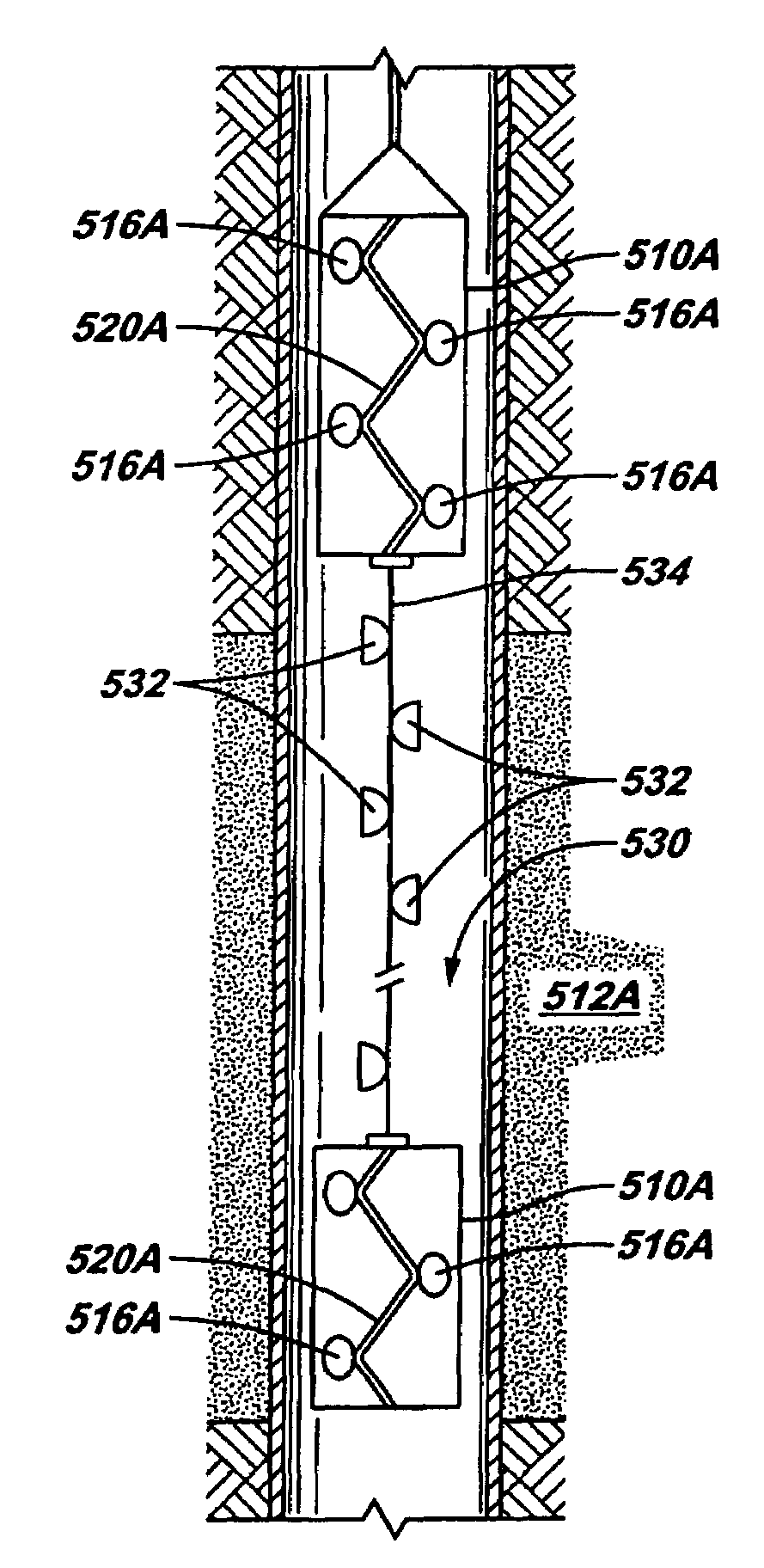
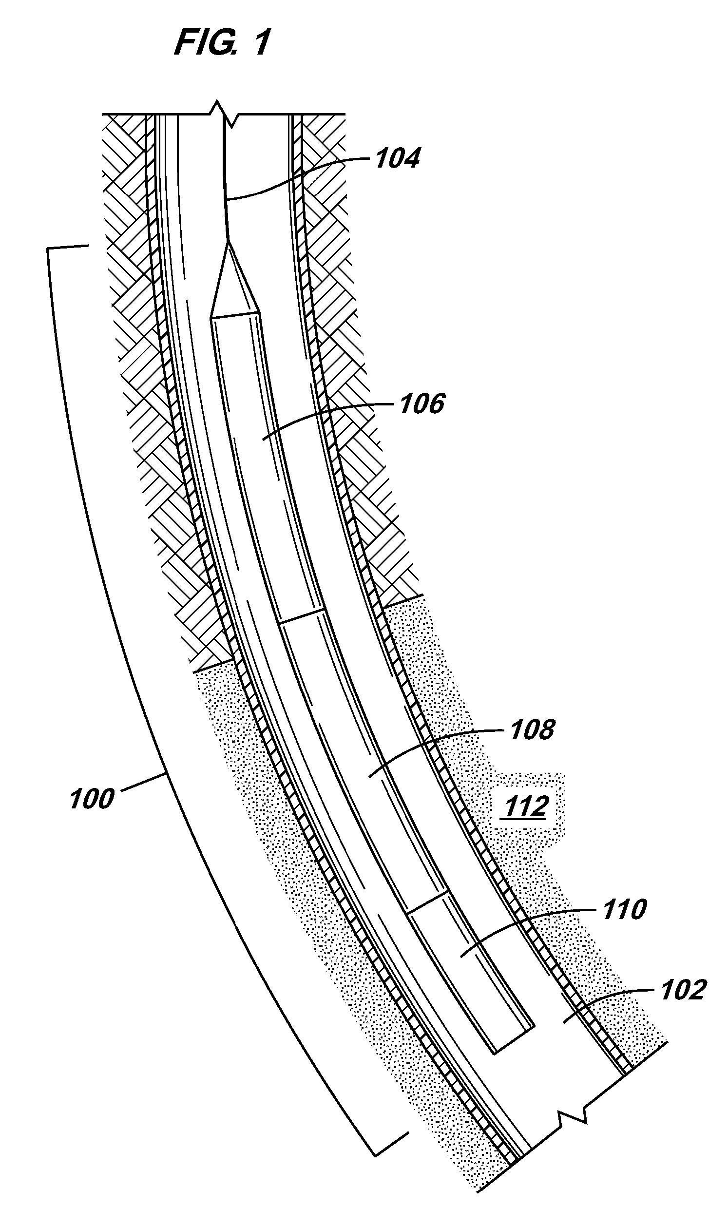
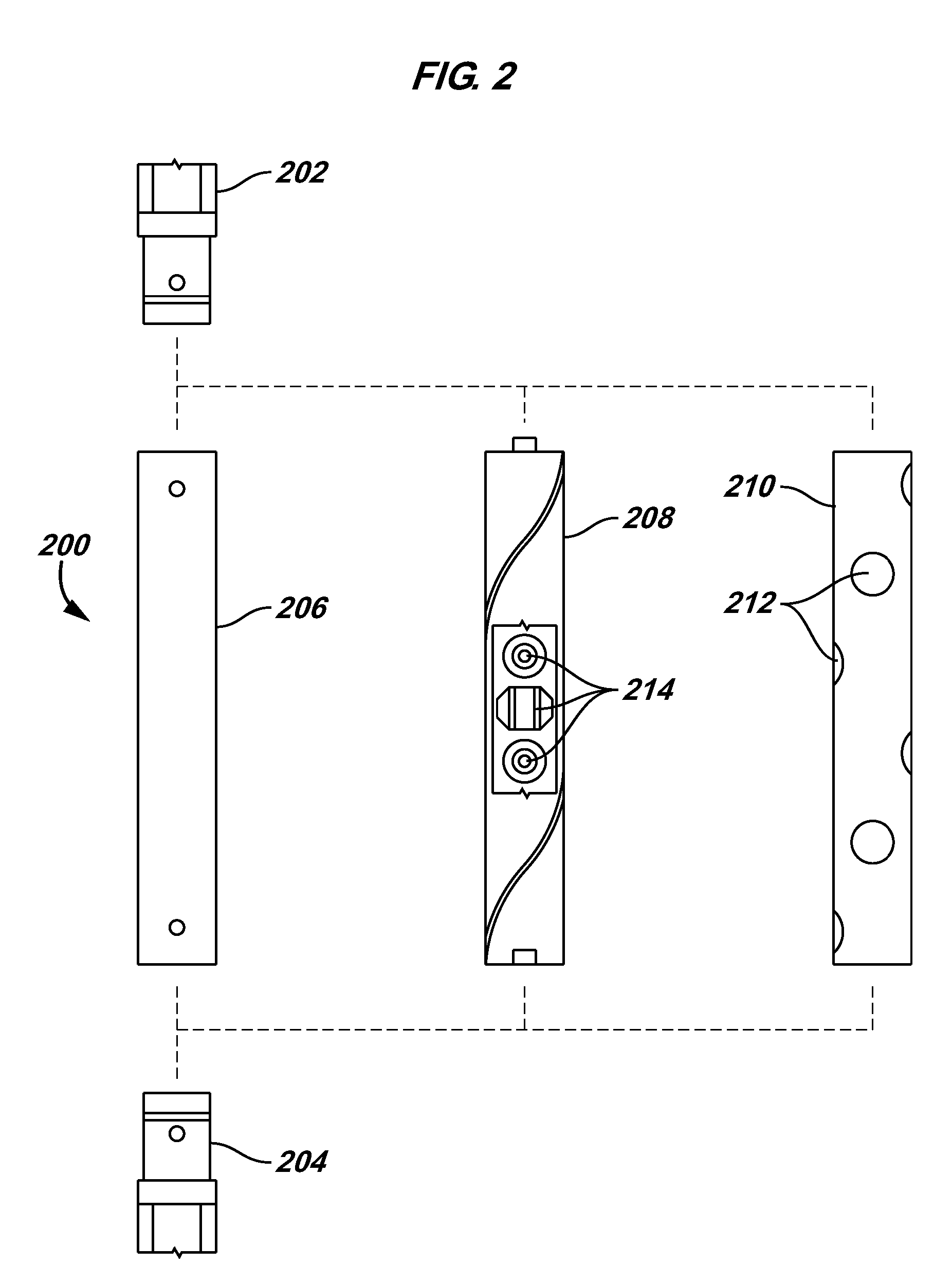
[0020]According to some embodiments of the invention, transient overbalance and underbalance pressure conditions are generated in a wellbore ...


PUM


Abstract

A method and apparatus for use in a wellbore includes running a tool string to an interval of the wellbore, and activating a first component in the tool string to create a transient underbalance pressure condition in the wellbore interval. Additionally, a second component in the tool string is activated to create a transient overbalance pressure condition in the wellbore interval, or vice versa.

Description

CROSS REFERENCE TO RELATED APPLICATIONS[0001]This is a continuation-in-part of U.S. Ser. No. 10 / 667,011, filed Sep. 19, 2003 now U.S. Pat. No. 7,182,138, which is a continuation-in-part of U.S. Ser. No. 10 / 316,614, filed Dec. 11, 2002, now U.S. Pat. No. 6,732,798, which is a continuation-in-part of U.S. Ser. No. 09 / 797,209, filed Mar. 1, 2001, now U.S. Pat. No. 6,598,682, which claims the benefit of U.S. Provisional Application Ser. Nos. 60 / 186,500, filed Mar. 2, 2000; 60 / 187,900, filed Mar. 8, 2000; and 60 / 252,754, filed Nov. 22, 2000. Each of the referenced applications is hereby incorporated by reference.BACKGROUND OF INVENTION[0002]The invention relates to improving reservoir communication within a wellbore.[0003]To complete a well, one or more formation zones adjacent a wellbore are perforated to allow fluid from the formation zones to flow into the well for production to the surface or to allow injection fluids to be applied into the formation zones. A perforating gun string m...

Claims


Application Information

Patent Timeline
IPC IPC(8): E21B43/117E21BE21B21/00E21B34/00E21B37/08E21B43/04E21B43/11E21B43/119E21B43/26E21B49/08
CPCE21B21/00F42D5/045E21B37/08E21B43/04E21B43/11E21B43/117E21B43/119E21B43/1195E21B43/26E21B49/08E21B49/087F42B3/02E21B37/00E21B2021/006E21B2034/002E21B21/085E21B2200/04E21B43/116
Inventor RATANASIRIGULCHAI, WANCHAIBEHRMANN, LAWRENCE A.MARTIN, ANDREW J.GOODMAN, KENNETH R.
Owner SCHLUMBERGER TECH CORP
Features
  • Generate Ideas
  • Intellectual Property
  • Life Sciences
  • Materials
  • Tech Scout
  • Unparalleled Data Quality
  • Higher Quality Content
  • 60% Fewer Hallucinations
Learn More