
Trailer dolly
a technology of trailers and dolly wheels, which is applied in the direction of transportation and packaging, transportation items, items transportation vehicles, etc., can solve the problems of trailers that no longer roll on their own wheels, trailers that cannot be loaded become very difficult to move in either a forward or rearward direction, so as to prevent damage to trailer tongues, trailer jacks, and associated components and wiring
- Summary
- Abstract
- Description
- Claims
- Application Information
AI Technical Summary
Benefits of technology
Problems solved by technology
Method used
Image

Examples
Embodiment Construction
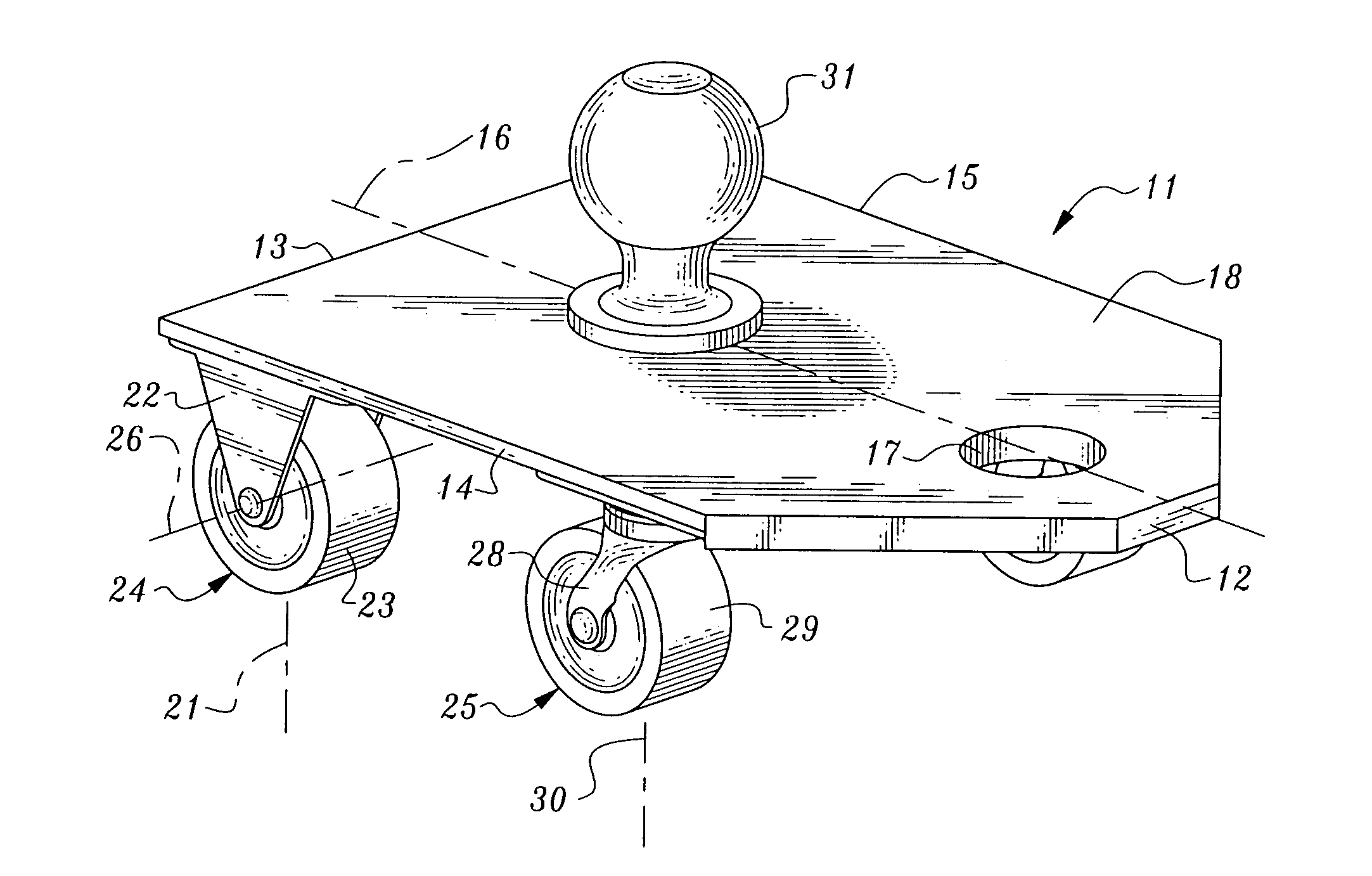
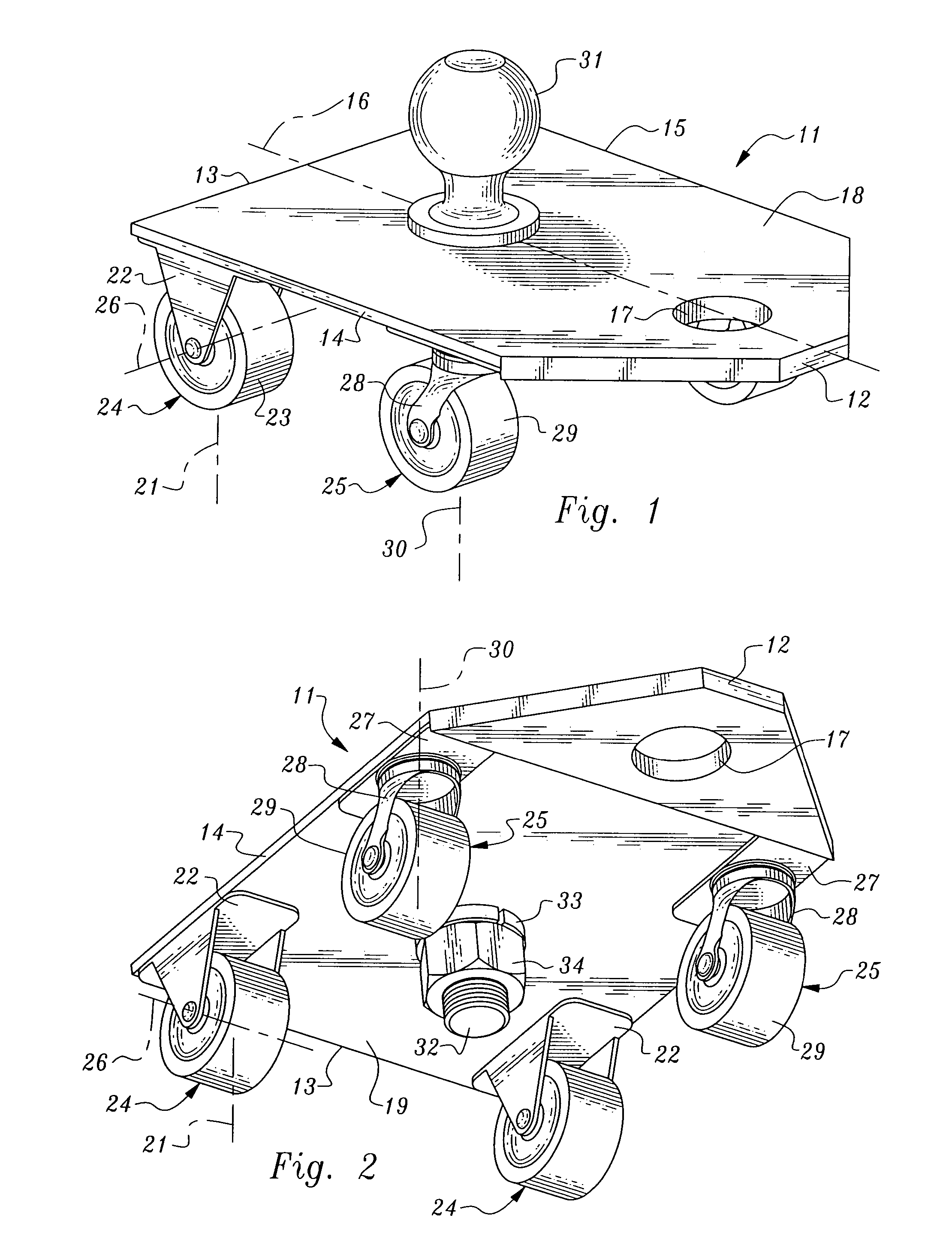
[0032]Turning now to the drawings, and in particular to FIGS. 1 and 2, the trailer dolly 10 of the present invention generally comprises a horizontal base plate 11, a first pair of wheels 24, a second pair of wheels 25, and a trailer hitch ball 31 mounted on an upper side 18 of said base plate 11.
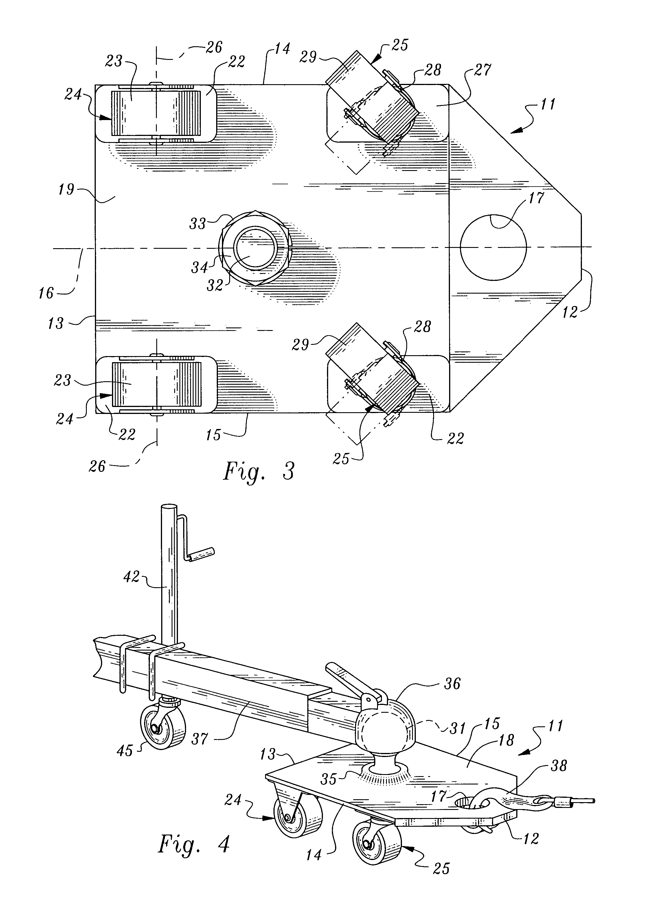
[0033]As illustrated in FIGS. 2 and 3, said first pair of wheels 24, are fixed from rotation about a first vertical axis 21 and having wheels 23 with an axis of rotation normal to said fore and aft axis 16. Said first pair of wheels 24 are mounted on a lower side 19 of said base plate 11, adjacent said rearward end 13 and adjacent said sides 14 and 15, respectively, on either side of said fore and aft axis 16. It will be appreciated that a fixed wheel mounting bracket 22 may be mounted by various means, including welding or bolting said mounting bracket 22 to said lower side 19 of saidbase plate 11.
[0034]As further illustrated in FIGS. 2 and 3, a second pair of wheels 25, being rotatable ab...
PUM
 Abstract
Description
Claims
Application Information