Zero insertion force electrical connector piece

a technology of electrical connectors and zero insertion force, which is applied in the direction of coupling parts, electrical apparatus, coupling contact members, etc., can solve the problems of insufficient installation space to accommodate or operate such assembly aids, the force required to join multi-poles, and the inability to produce multi-poles

Inactive Publication Date: 2007-11-06
KOSTAL KONTAKT SYST
View PDF11 Cites 13 Cited by
  • Summary
  • Abstract
  • Description
  • Claims
  • Application Information

AI Technical Summary

Benefits of technology

[0019]The activation elements of a multi-pole, zero force insertion electrical connector part in accordance with an embodiment of the present invention may be mutually actuated without a great exertion of force. This is a result of inclined positioning surfaces between the activation elements and the associated sleeve contacts. Alternatively, this is a result of positioning cams advantageously associated with the activation elements and the associated sleeve contacts. The individual association of an activation element with a sleeve contact allows individual rows of activation elements, or individual groups of sleeve contacts, to be mutually activated.
[0020]In an embodiment, a sleeve contact (i.e., a contact socket) includes two contact members oppositely situated with respect to the plug receptacle of the sleeve contact. Each contact member has two adjacent contact regions. A contact member section separates the contact regions from one another. The contact member section bulges outward relative to the activation element. Obliquely extending surfaces of the bulge are used as positioning bevels for a positioning cam of the activation element. The positioning cam acts on the middle region of the bulge in the activated position of the activation element to thereby enable the activation element to apply the desired contact force to the contact regions.

Problems solved by technology

This zero insertion force connector is not suitable for producing a multi-pole, plug-in connector such as a multi-row, plug-in connector.
The force required to join multi-pole, complementary plug-in connector parts together is considerable.
However, in many locations inside a vehicle in which such plug-in connector parts are connected to one another, there is not enough installation space available to accommodate or operate such assembly aids.

Method used


Image

  • Zero insertion force electrical connector piece
  • Zero insertion force electrical connector piece
  • Zero insertion force electrical connector piece

Examples


Embodiment Construction

)

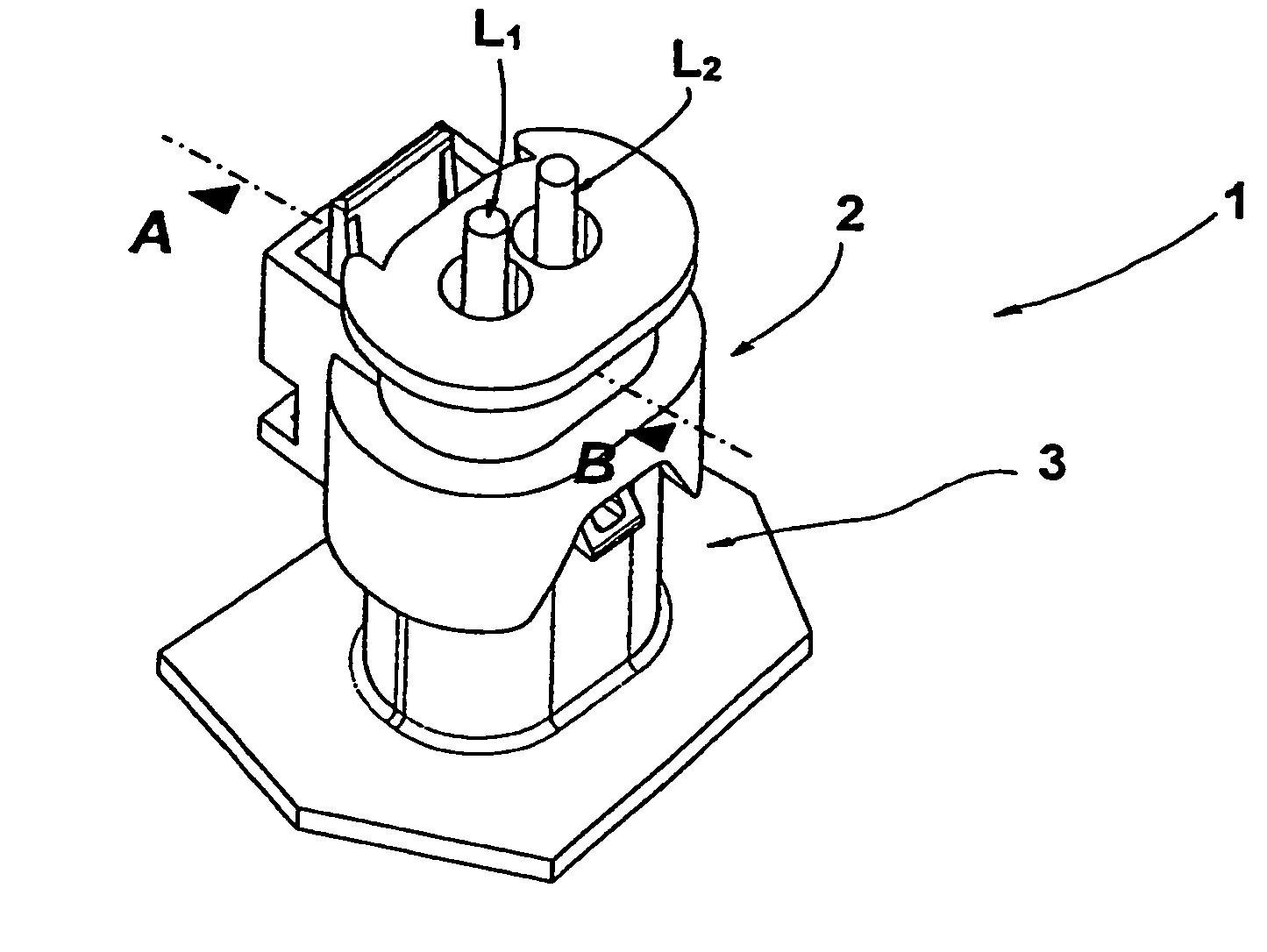
[0032]Referring now to FIG. 1, a perspective view of a zero insertion force electrical connector 1 in accordance with an embodiment of the present invention is shown. Connector 1 is a multi-pole, plug-in connector. Connector 1 includes first and second zero insertion force electrical connector parts 2, 3. Connector parts 2, 3 are complementary to one another such that the connector parts may be electrically and mechanically connected to one another to form connector 1. Each of connector parts 2, 3 is a multi-pole, plug-in connector part having two poles. First connector part 2 is a socket part. Second connector part 3 bears electrical plug contacts. In this embodiment, second connector part 3 is integrally molded onto the outer wall of a control device. As shown in FIG. 1, first and second connector parts 2, 3 are connected to one another thereby forming connector 1.

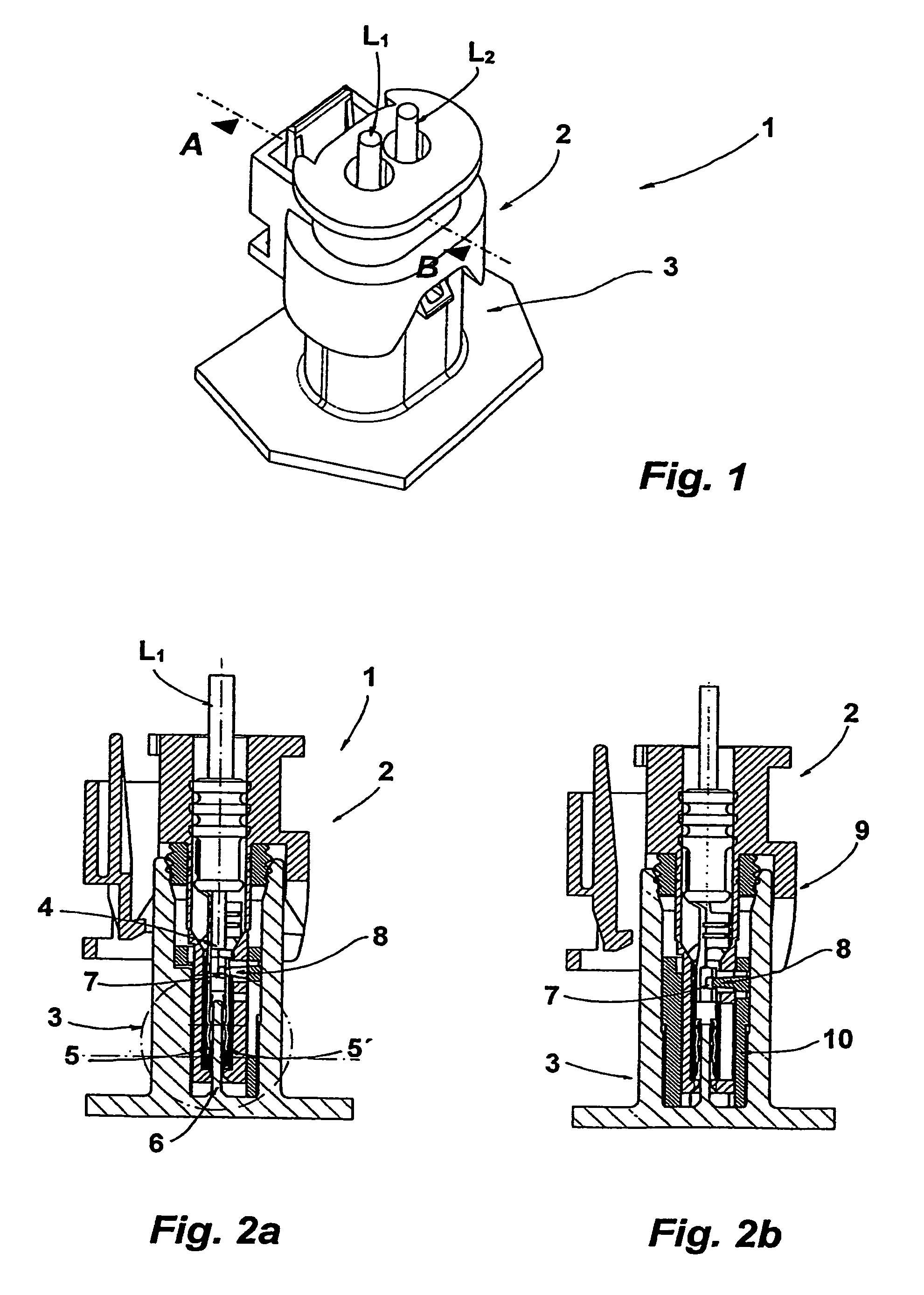
[0033]Referring now to FIGS. 2A and 2B, with continual reference to FIG. 1, sectional views of connector 1 along the ...


PUM


Abstract

A zero insertion force electrical connector part includes a sleeve contact (socket contact) and an activation element associated with the sleeve contact. The sleeve contact has contact members with a plug contact receptacle situated between the contact members for receiving an electrical plug contact. Each contact member has a contact region. The activation element is enclosed around the contact members. The activation element is displaceable relative to the sleeve contact between non-activated and activated positions. The activation element applies a contact force to the contact members of the sleeve contact which forces the contact regions against a plug contact inserted into the plug contact receptacle of the sleeve contact to make contact with the plug contact while the activation element is in the activated position.

Description

CROSS-REFERENCE TO RELATED APPLICATIONS[0001]This is a continuation of International Application PCT / EP2005 / 003222, published in German, with an international filing date of Mar. 26, 2005, which claims priority to DE 10 2004 015 344.2 filed Mar. 30, 2004, the disclosures of which are both hereby incorporated by reference.BACKGROUND OF THE INVENTION[0002]1. Field of the Invention[0003]The present invention relates to zero insertion force electrical connectors.[0004]2. Background Art[0005]Zero insertion force connectors are plug-in connectors used in electronic devices for contacting individual modules, flexible films, and printed circuit boards. The terms “zero insertion force connector” and “zero insertion force connector piece” are used because the plug-in connector parts of these connectors may be contacted with application of relatively little force.[0006]DE 197 42 400 A1 describes a zero insertion force connector for connecting two printed circuit boards. This connector includes...

Claims


Application Information

Patent Timeline
Patent Type & Authority Patents(United States)
IPC IPC(8): H01R13/15H01R13/62H01R13/193
CPCH01R13/193
Inventor MOHS, WOLFGANG
Owner KOSTAL KONTAKT SYST
Why Eureka
Try Eureka