Electrical meter system with color coding features

a technology of color coding and electric meters, applied in the field of electric meters, can solve the problems of tangled or twisted leads, wires or cables extending between the power meters and multiple loads, and the inability to shut down the system to correct wiring mistakes, etc., and achieve the effect of minimizing the number of wires from different loads while connecting these loads to the electrical measuring devi

Inactive Publication Date: 2007-11-13
ELECTRO INDUSTRIES GAUGE TECH
View PDF5 Cites 36 Cited by
  • Summary
  • Abstract
  • Description
  • Claims
  • Application Information

AI Technical Summary

Benefits of technology

[0009]The above and other objectives are attained by an installation system and method in which a plurality of loads, each of which is characterized by a respective pair of uniformly colored wires, are connected to a corresponding input, which is the same color as each pair, of an electrical metering device. As a result, crossing wires from different loads while connecting these loads to an electrical measuring device is minimized.

Problems solved by technology

Additionally, having a plurality of power consuming loads often requires precise measurements associated with each of these loads.
However, quite often, leads, wires or cables extending between the power meter and multiple loads are tangled or twisted.
In this case, the any reading associated with a load is skewed and the information thus received can lead to serious problems.
Because these electrical meters are often installed in critical applications, shutting a system down to correct for wiring mistakes is often impossible.
As a result, the meter ends up reading incorrect data for an extended period of time, e.g., until an entire plant shutdown.

Method used


Image

  • Electrical meter system with color coding features
  • Electrical meter system with color coding features
  • Electrical meter system with color coding features

Examples


Embodiment Construction

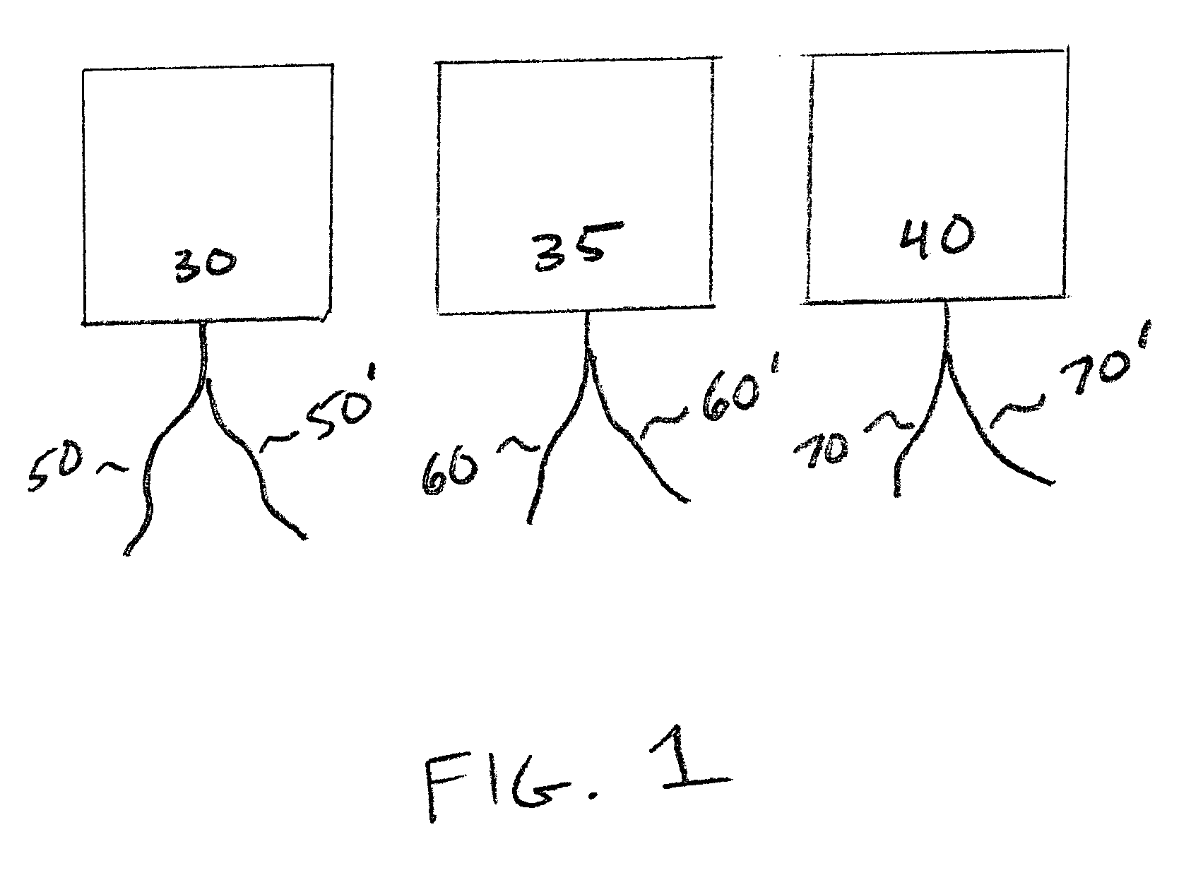
[0013]Preferred embodiments of the present invention will now be described in detail herein below with reference to the annexed drawings. In the following description, a detailed description of known functions and configurations incorporated herein has been omitted for conciseness.

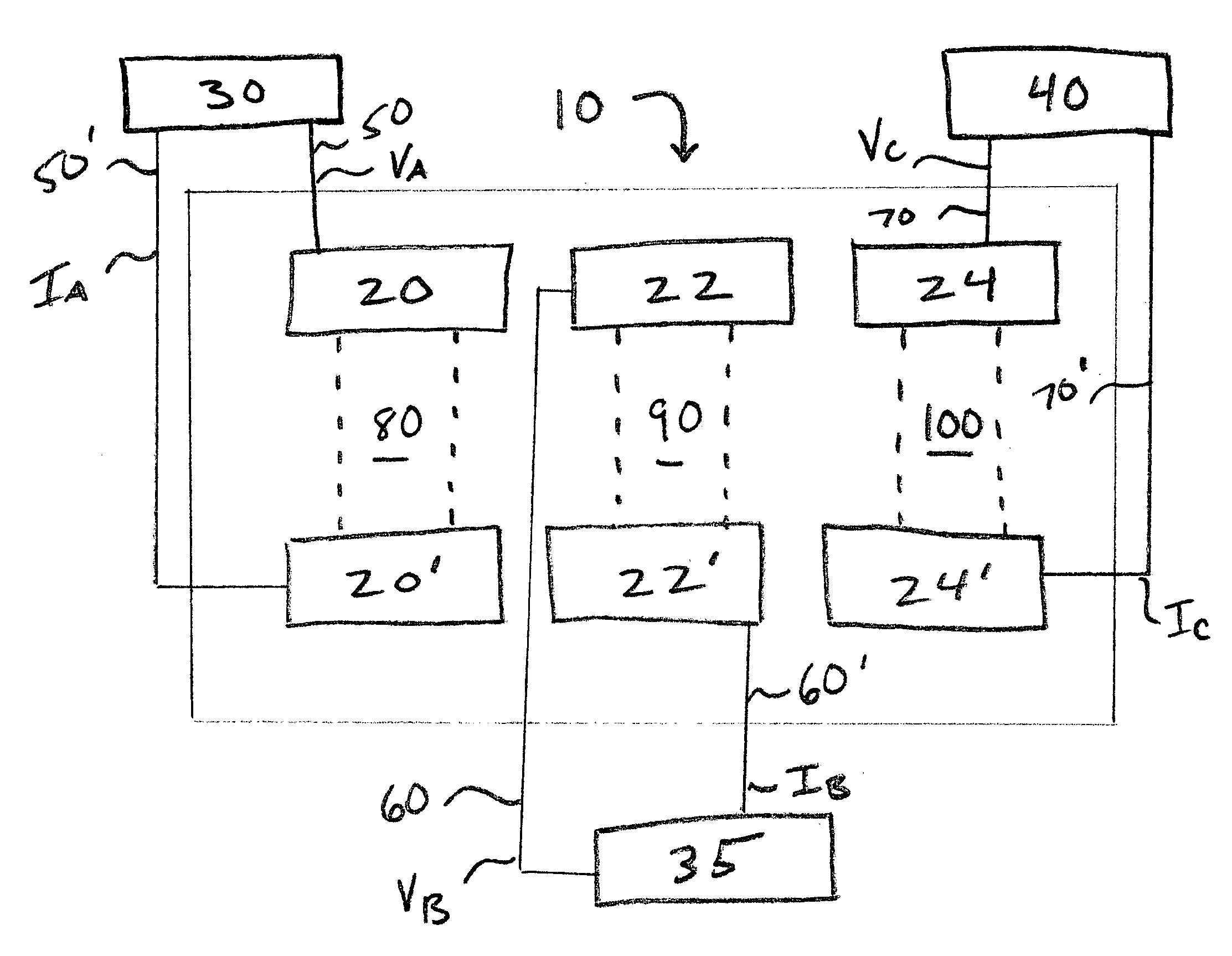
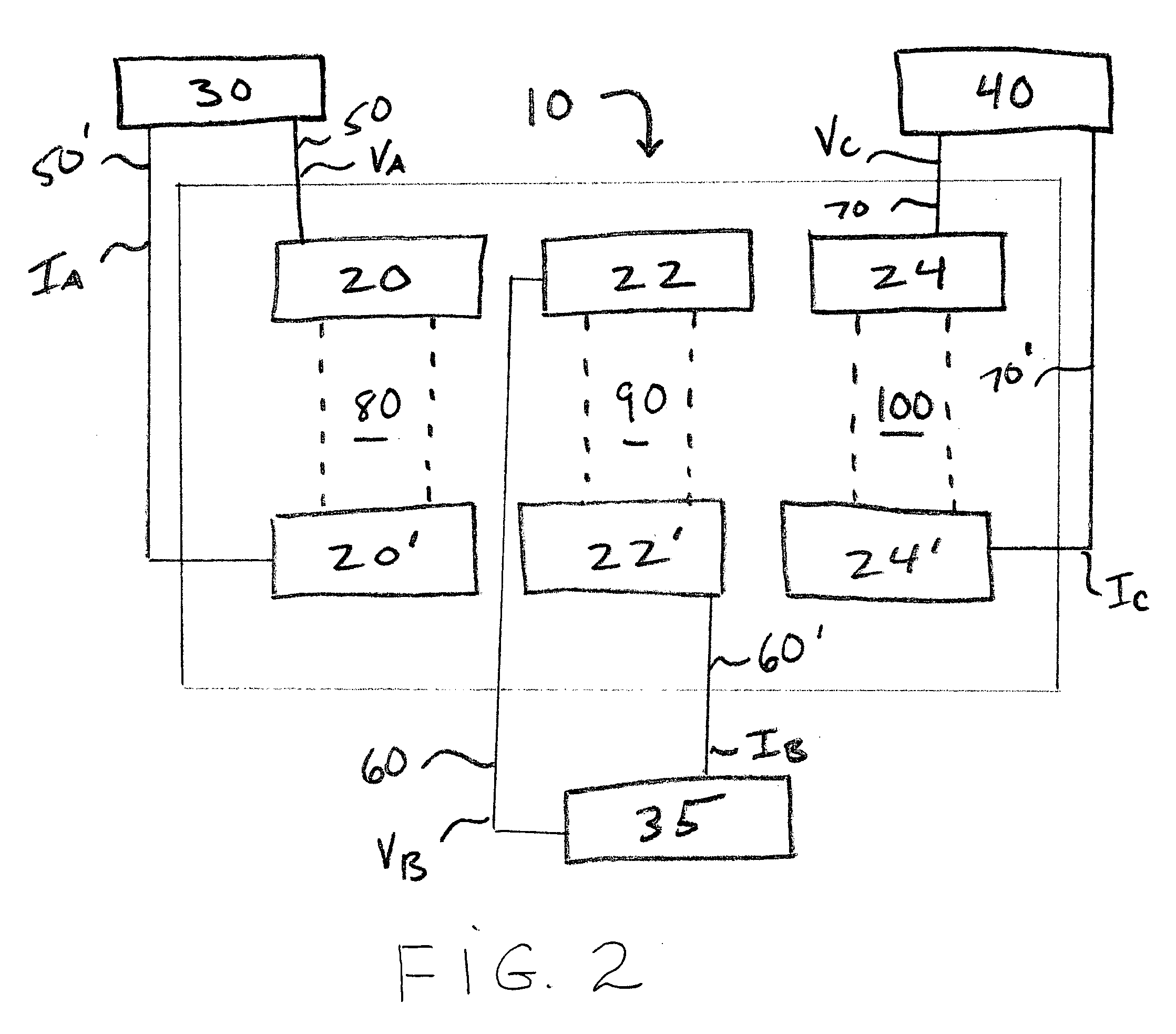
[0014]FIG. 1 is block diagram illustrating an inventive installation system including a plurality of loads, each characterized by a pair of current and voltage wires, which are uniquely color coded, and FIG. 2 is a diagrammatic view illustrating one of embodiments of the invention.

[0015]Referring to FIGS. 1 and 2, an inventive installation system 10 includes a plurality of wires pairs 50 and 50′, 60 and 60′, and 70 and 70′, which extending between loads 30, 35, and 40 and a metering device 10, respectively. Wires 50, 60, and 70 each correspond to the voltage of their respective pairs, and wires 50′, 60′, and 70′ each correspond to the current of their respective pairs. Further, to avoid crossing the voltag...


PUM


Abstract

A communication system between a plurality of electrical loads and at least one electrical measurement device is configured with a plurality of wires grouped in pairs. Each pair of wires is uniquely color coded to facilitate installation of each electrical load.

Description

BACKGROUND OF THE INVENTION[0001]1. Field of the Invention[0002]The invention relates generally to electrical metering, and more specifically to an electrical system ergonomically configured to facilitate installation of and provide reliable reading of electrical parameters of a plurality of loads.[0003]2. Description of the Related Art[0004]Currently, various electrical meters are used for high accuracy measurement over a wide frequency bandwidth. Additionally, having a plurality of power consuming loads often requires precise measurements associated with each of these loads. For example, it may be desirable to measure voltage, current, watts, vars, frequency, power, watt-hours, var / hours, demand, harmonics, etc., for each load.[0005]Accordingly, in the conventional art, installation of a system including at least one power meter and multiple loads is typically realized by wiring and connecting each of these loads to the power meter. However, quite often, leads, wires or cables ext...

Claims


Application Information

Patent Timeline
Patent Type & Authority Patents(United States)
IPC IPC(8): G01R22/00
CPCG01R11/04
Inventor KAGAN, ERRAN
Owner ELECTRO INDUSTRIES GAUGE TECH
Why Eureka
Try Eureka