Three-spool by-pass turbojet with a high by-pass ratio

a turbojet and by-pass technology, applied in the direction of machines/engines, sustainable transportation, mechanical equipment, etc., can solve the problems of reducing efficiency, increasing the weight of the engine, and affecting the efficiency of the engine, so as to optimize the matching of the rear fan to the different engine speed

Active Publication Date: 2007-11-27
SN DETUDE & DE CONSTR DE MOTEURS DAVIATION S N E C M A
View PDF9 Cites 57 Cited by
  • Summary
  • Abstract
  • Description
  • Claims
  • Application Information

AI Technical Summary

Benefits of technology

[0004]The object of the invention is to make it possible to optimize matching of the rear fan to different engine speeds.

Problems solved by technology

Nevertheless, gearing increases the weight of the engine considerably and also reduces efficiency.
At other speeds, however, efficiency is necessarily reduced.

Method used


Image

  • Three-spool by-pass turbojet with a high by-pass ratio
  • Three-spool by-pass turbojet with a high by-pass ratio

Examples


Embodiment Construction

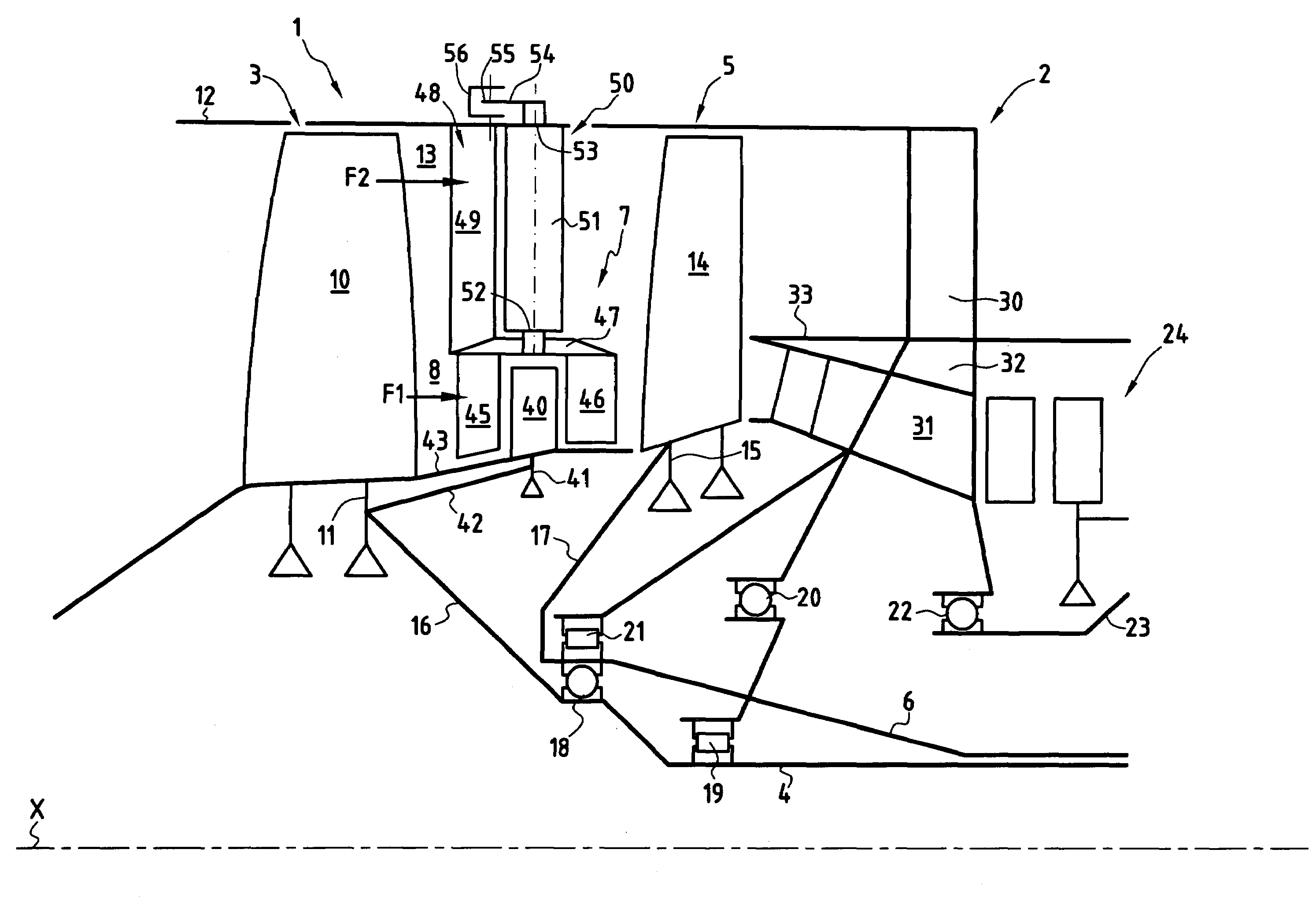
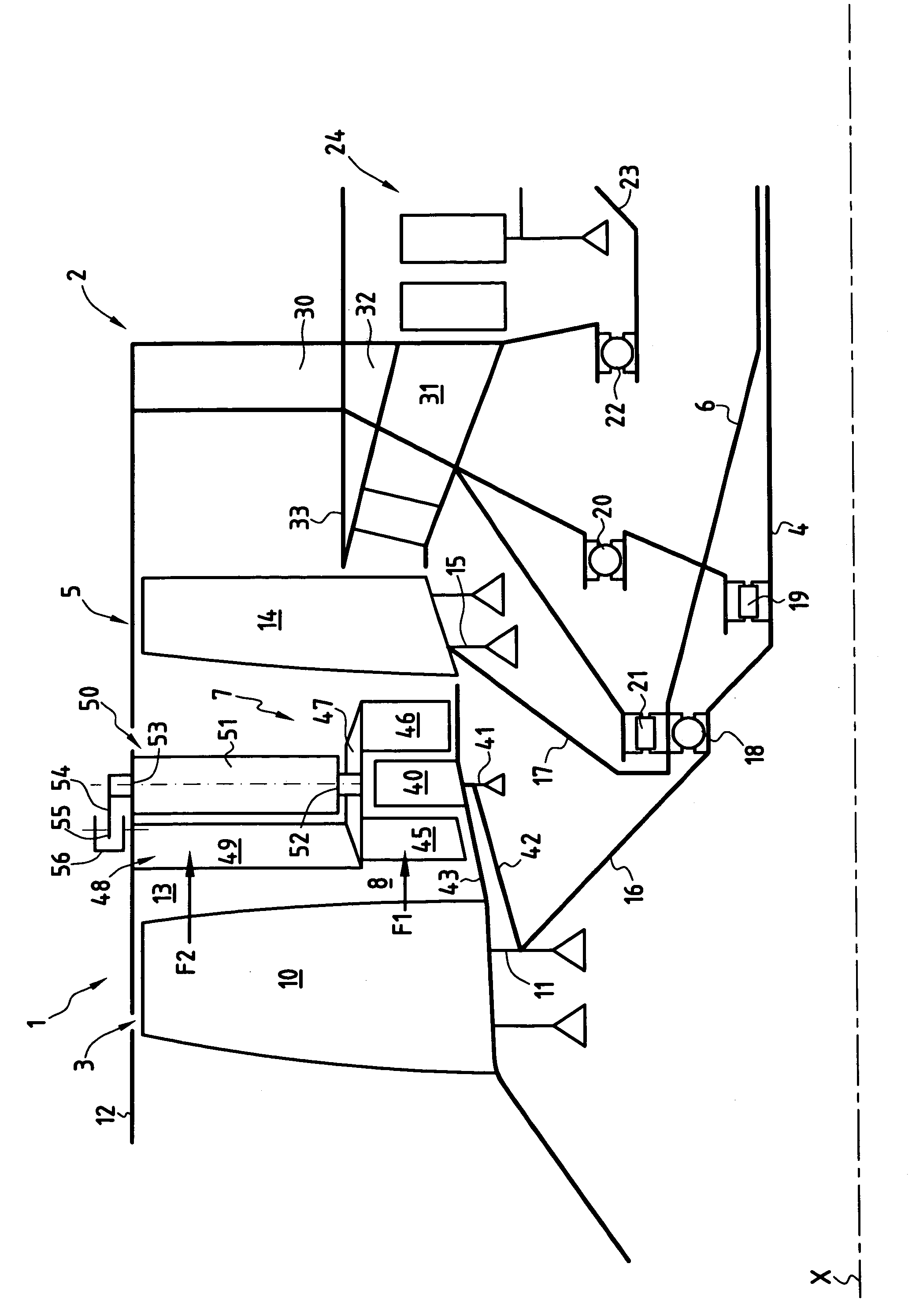
[0014]The drawing is a diagram which shows the front 1 of a turbojet of axis X, which has a front fan 3 and a rear fan 5 at the front of an intermediate casing 2, said front fan 3 being driven by an inner drive shaft 4, said rear fan 5 being driven by an intermediate drive shaft 6 coaxial with the inner shaft 4 and surrounding said inner shaft, and a low-pressure compressor disposed axially between the front fan 3 and the rear fan 5 in order to compress the air coming into the channel 8 for the main air flow F1.

[0015]The front fan 3 has blades 10 which extend from the periphery of a wheel 11 to a fan casing 12 that defines the outside of the channel 13 for the by-pass air F2.

[0016]The rear fan likewise has blades 14 which extend from the periphery of a wheel 15 to the fan casing 12, through the channel 8 for the main air flow F1 and through the channel 13 for the by-pass air F2.

[0017]The wheel 11 of the front fan 3 is connected to the inner shaft 4 by a cone 16, and the wheel 15 of ...


PUM


Abstract

The invention relates to aerodynamically matching the rear fan of a turbojet having two fans and a low-pressure compressor at the front of the intermediate casing, said fans being driven by two independent shafts. Said compressor is disposed between the blades of the two fans and includes at least one ring of rotor blades around the periphery of a wheel driven by the drive shaft for the front fan, and at least two grids of stator vanes disposed on either side of the ring of rotor blades and inside a grid carrier ring. A stationary outer grid and a stator of variable pitch connect the ring to the fan casing.

Description

[0001]The invention relates to a three-spool by-pass turbojet with a high by-pass ratio, the turbojet having a front fan and a rear fan at the front of an intermediate casing that presents an outer structural grid in the by-pass flow and an inner structural grid in the main air flow, the fans having blades that extend radially outwards to a fan casing, which fan casing defines the outside of the by-pass air flow, the turbojet also having a low-pressure compressor for compressing the air coming into the channel for the main air flow, said front fan and said rear fan being rotated directly, and separately, by two shafts that are coaxial.BACKGROUND OF THE INVENTION[0002]In a modern, high-power turbojet with a high by-pass ratio, the fan has a large diameter, and the peripheral speed at the tips of the blades is proportional both to this diameter and to the speed of rotation of the fan. In order to obtain good efficiency, the peripheral speed must be lower than the speed of sound. In a ...

Claims


Application Information

Patent Timeline
Patent Type & Authority Patents(United States)
IPC IPC(8): F02K3/065F02K3/072F02C9/20F01D17/16F02C3/067F02C3/073F02K3/06
CPCF01D17/162F02K3/072F02C3/067Y02T50/671Y02T50/60
Inventor BART, JACQUESLACORRE, FABIENNELEBRET, YANNLE ROUSSEAU, VANESSAMOREL, PATRICK
Owner SN DETUDE & DE CONSTR DE MOTEURS DAVIATION S N E C M A
Why Eureka
Try Eureka