

Methods and apparatus for bi-stable actuation of displays
a display and stability technology, applied in the field of video displays, can solve the problems that backlit displays using mechanical light modulators have not yet demonstrated sufficiently attractive combinations of brightness and low power, and achieve the effect of reducing rotation or other movemen
- Summary
- Abstract
- Description
- Claims
- Application Information
AI Technical Summary
Benefits of technology
Problems solved by technology
Method used
Image

Examples
Embodiment Construction
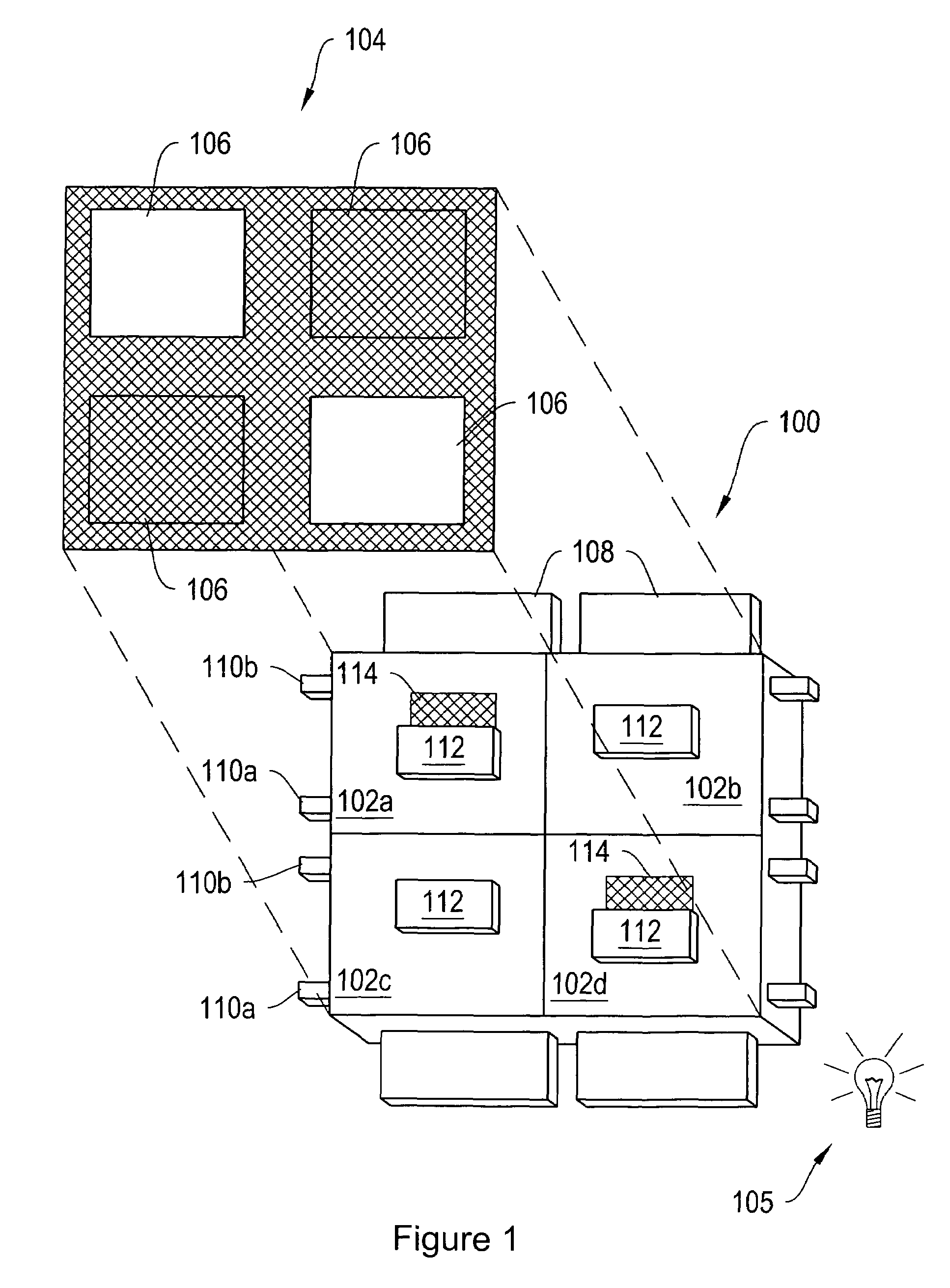
[0047]FIG. 1A is an isometric view of a display apparatus 100, according to an illustrative embodiment of the invention. The display apparatus 100 includes a plurality of light modulators, in particular, a plurality of shutter assemblies 102a-100d (generally “shutter assemblies 102”) arranged in rows and columns. In general, a shutter assembly 102 has two states, open and closed (although partial openings can be employed to impart grey scale). Shutter assemblies 102a and 100d are in the open state, allowing light to pass. Shutter assemblies 102b and 100c are in the closed state, obstructing the passage of light. By selectively setting the states of the shutter assemblies 102a-100d, the display apparatus 100 can be utilized to form an image 104 for a projection or backlit display; if illuminated by lamp 105. In another implementation the apparatus 100 may form an image by reflection of ambient light originating from the front of the apparatus. In the display apparatus 100, each shutt...
PUM
 Abstract
Description
Claims
Application Information