Fluid-filled type vibration damping device

a technology of vibration damping device and fluid filling, which is applied in the direction of shock absorbers, machine supports, mechanical equipment, etc., can solve the problems of noise and vibration being produced at a level noticeable to passengers in the vehicle, transitory high level of negative pressure within, and achieving desired vibration damping characteristics , the effect of preventing large vibration or nois

Active Publication Date: 2007-12-11
SUMITOMO RIKO CO LTD
View PDF10 Cites 19 Cited by
  • Summary
  • Abstract
  • Description
  • Claims
  • Application Information

AI Technical Summary

Benefits of technology

[0012]It is therefore one object of this invention to provide a fluid filled type vibration damping device of novel construction, which is able to reliably and accurately reduce the extent of noise and vibration occurring during input of large shocking vibration load, while also ensuring sufficient fluid flow through the orifice passage when vibration to be damped is input.

Problems solved by technology

In a fluid filled type vibration damping device of this kind, when a large vibrational load is input across the first mounting member and the second mounting member, noise and vibration are sometimes emitted by the vibration damping device.
Specifically, in the event that an automotive vehicle employing a fluid filled type vibration damping device of the construction described above as an engine mount should happen to drive over grooved pavement or speed bumps, such noise and vibration can be produced at a level noticeable to passengers in the vehicle.
Such noise and vibration occurs when, during input of impulsive vibration, the flow of the fluid through the orifice passage between the pressure-receiving chamber and the equilibrium chamber cannot keep up, so that a transitory high level of negative pressure occurs within the pressure-receiving chamber.
This may cause the problem of noise and vibration mentioned previously.
Consequently, any pressure difference between the pressure-receiving chamber and the equilibrium chamber is eliminated by the flow of the fluid through the slit, which can make it difficult to ensure adequate relative pressure fluctuations between the pressure-receiving chamber and the equilibrium chamber.
As a result, it becomes difficult to ensure adequate fluid flow level through the orifice passage, posing the risk of difficulty in sufficiently attaining the desired vibration damping action on the part of the orifice passage.
Additional research carried out by the inventors has shown that the fluid filled vibration damping device taught in JP-A-2003-148548 is not yet satisfactory in all instances.
Due to repeated opening and closing or due to change over time, the rubber elastic body constituting the valve means can experience deformation or deterioration, posing the risk that it will no longer be able to maintain the short-circuit passage opening in the fluid-tightly closed state even where the level of negative pressure in the pressure-receiving chamber is lower than the predetermined negative pressure.
Additionally, due to repeated elastic deformation, the rubber elastic body per se may rupture.
Also, depending on the required properties, elastic deformation of the valve means composed of the rubber elastic body may not afford sufficient accuracy of recovery to initial shape.
Furthermore, with valve means employing a rubber elastic body, variability in dimensions and shape tends to occur readily, making it difficult to attain opening and closing of the valve means with the predetermined negative pressure as threshold, at a high level of accuracy.

Method used


Image

  • Fluid-filled type vibration damping device
  • Fluid-filled type vibration damping device
  • Fluid-filled type vibration damping device

Examples


Embodiment Construction

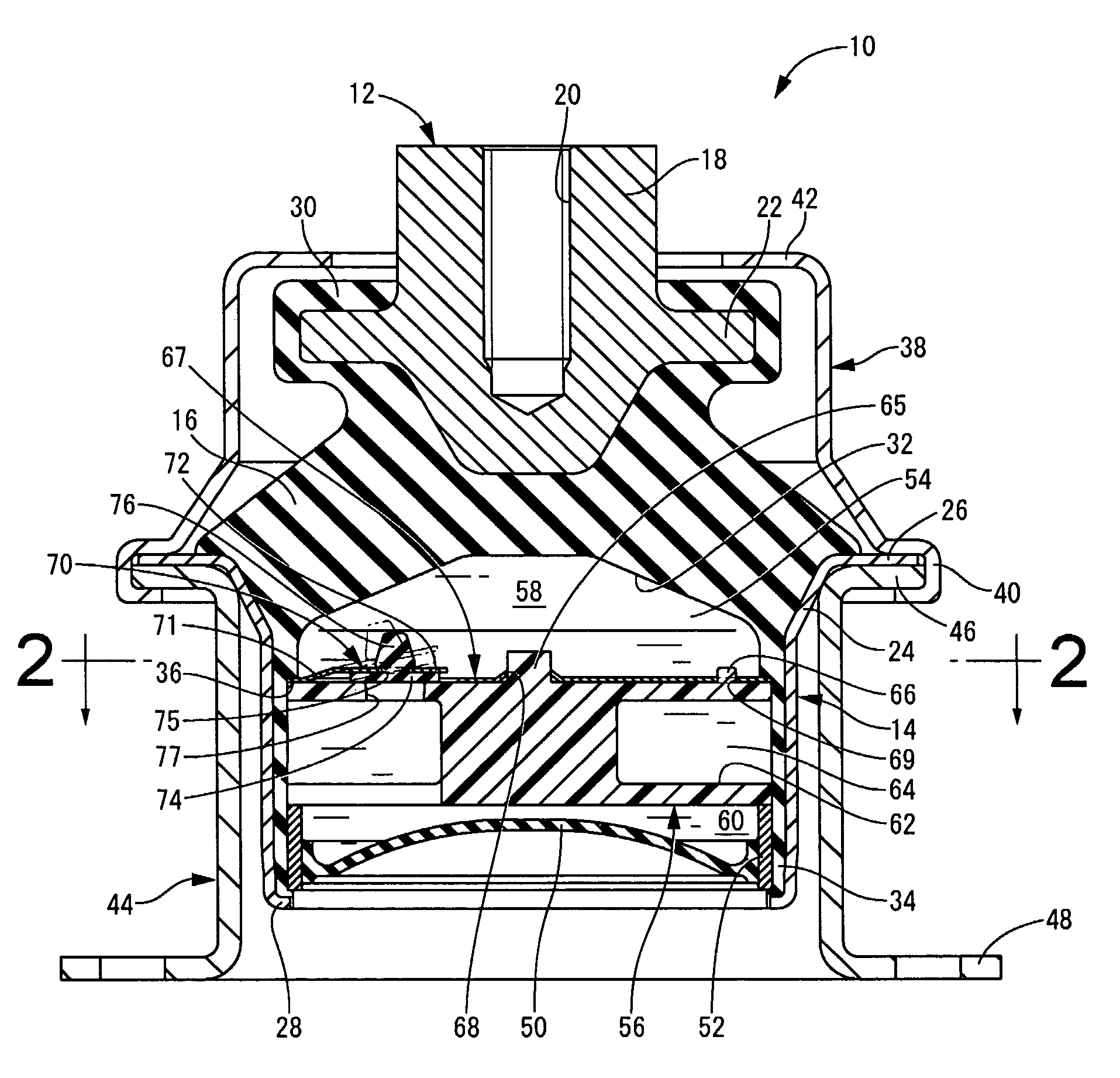
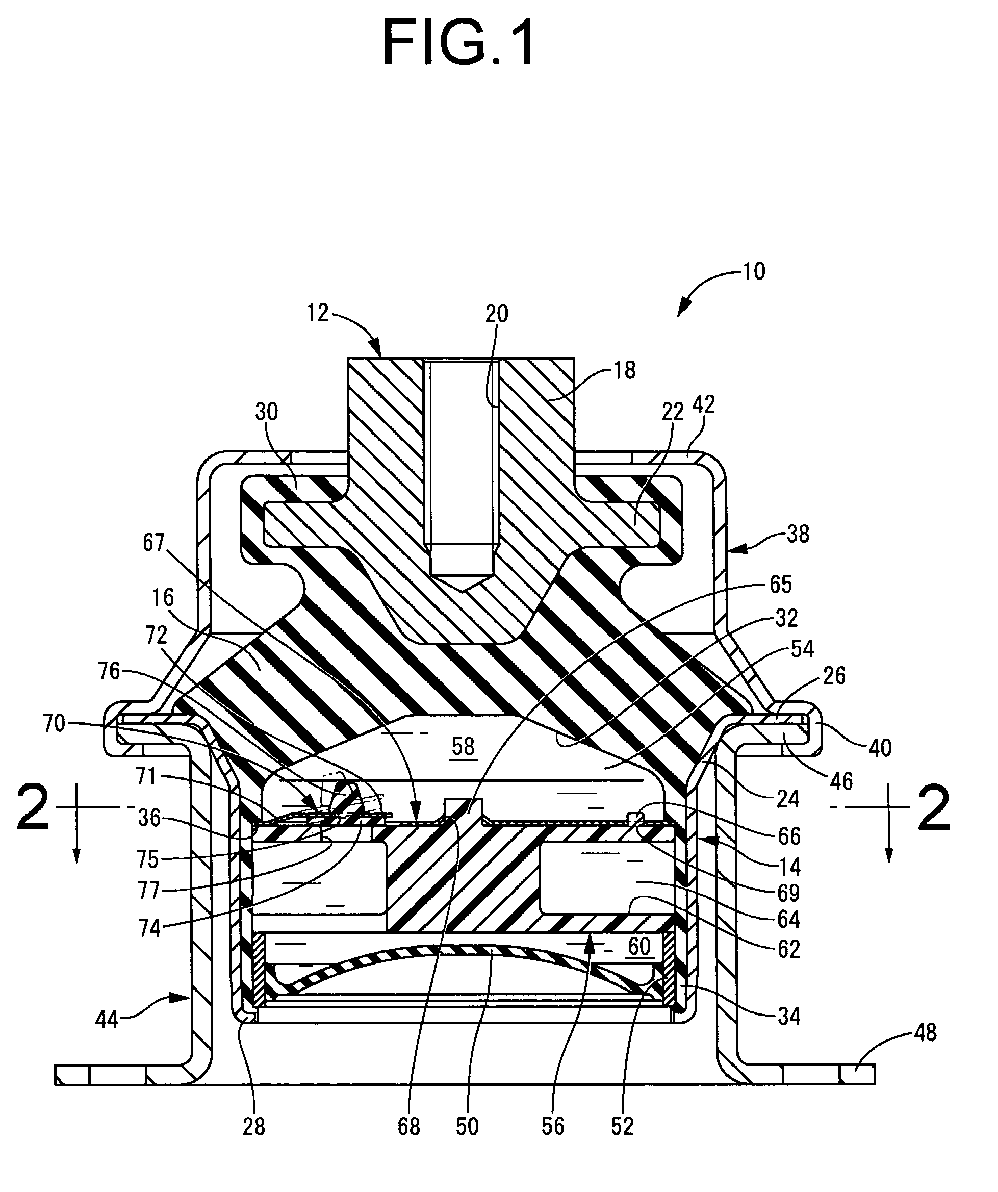
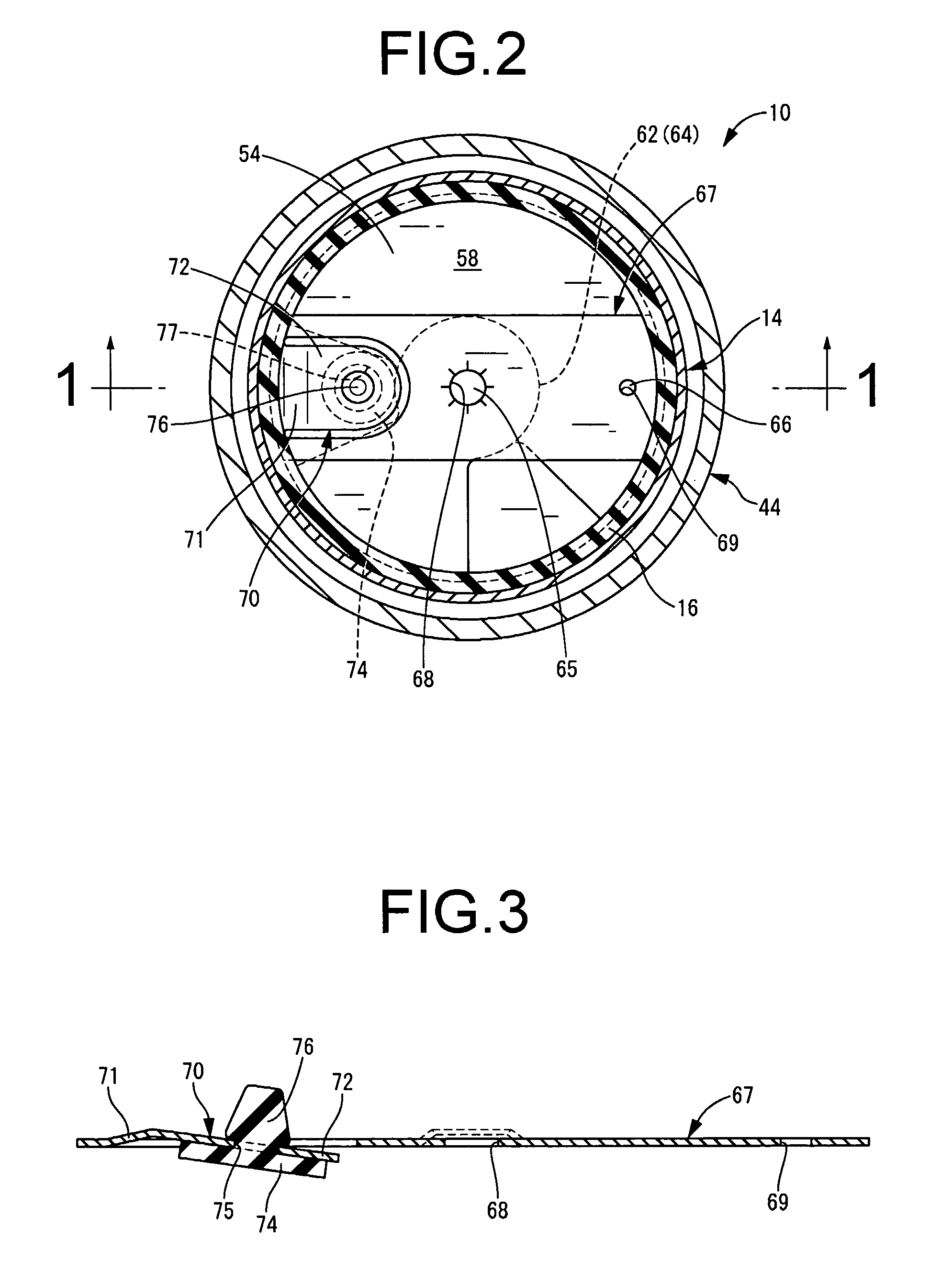
[0041]Referring first to FIG. 1 and FIG. 2, there is depicted a fluid filled type vibration damping device in the form of an automotive engine mount 10 of construction according to a first embodiment of the invention. This engine mount 10 includes a first mounting member 12 of metal and a second mounting member 14 of metal and a main rubber elastic body 16 elastically connecting the first and second mounting members 12, 14. By attaching the first mounting member 12 to a power unit (not shown) of an automotive vehicle and attaching the second mounting member 14 to a body (not shown) of the vehicle, the power unit is supported in vibration-damping fashion on the vehicle body. In the description hereinbelow, the vertical direction shall as general rule refer to the vertical direction in FIG. 1.

[0042]To describe in detail, the first mounting member 12 has an inverted, generally frustoconical block shape with an integrally formed threaded portion 18 projecting upward from its large-diame...


PUM


Abstract

A fluid filled type vibration damping device includes: a main rubber elastic body elastically connecting first and second mounting members; a partition member supported by the second mounting member; a pressure-receiving chamber partially defined by the elastic body and having a non-compressible fluid sealed therein; an equilibrium chamber partially defined by a flexible film and having the non-compressible fluid therein. The chambers are formed to either side of the partition member and an orifice passage permits a fluid communication between the two chambers. A short-circuit passage is formed so that the pressure-receiving and equilibrium chambers are able to be short-circuited through the short-circuit passage. A valve is used for switching the short-circuit passage, and a metal spring is used for holding the valve in a closed state at a predetermined initial level of elastic deformation.

Description

INCORPORATED BY REFERENCE[0001]The disclosures of Japanese Patent Applications No. 2005-267427 filed on Sep. 14, 2005 and No. 2006-052971 filed on Feb. 28, 2006, each including the specification, drawings and abstract are incorporated herein by reference in their entirety.BACKGROUND OF THE INVENTION[0002]1. Field of the Invention[0003]The present invention relates to a fluid filled type vibration damping device designed to produce vibration damping action based on flow action of a non-compressible fluid sealed therein, and more particularly to a fluid filled type vibration damping device suitable for use as an automotive engine mount, body mount, difference mount, or the like, for example.[0004]2. Description of the Related Art[0005]In the field of vibration damping devices for installation between components making up a vibration transmission system, it has been proposed to utilize vibration damping action based on the flow action, e.g. the resonance action, of a non-compressible f...

Claims


Application Information

Patent Timeline
Patent Type & Authority Patents(United States)
IPC IPC(8): F16F13/08
CPCF16F13/262F16F13/105
Inventor HAPPOU, HIROAKIMURAMATSU, ATSUSHIUENO, HIROYUKITAKESHIMA, SATORU
Owner SUMITOMO RIKO CO LTD
Why Eureka
Try Eureka