Frame member and box combination for recessing an electrical box and cover assembly

a technology of frame member and box combination, which is applied in the direction of electrical apparatus casing/cabinet/drawer, installation of lighting conductors, coupling device connections, etc., can solve the problems of lawnmowers, other hazards, and easy damage of outward-extending electrical box and cover assemblies

Active Publication Date: 2008-01-15
ARLINGTON INDS
View PDF10 Cites 38 Cited by
  • Summary
  • Abstract
  • Description
  • Claims
  • Application Information

AI Technical Summary

Benefits of technology

[0011](5) The current frame member and electrical box combination provides, when used to house a duplex outlet, an electrical box and a spacious protective enclosure for protecting the plug en

Problems solved by technology

Outward-extending electrical box and cover assemblies, though they cover the front of the box, are prone to damage by lawn

Method used


Image

  • Frame member and box combination for recessing an electrical box and cover assembly
  • Frame member and box combination for recessing an electrical box and cover assembly
  • Frame member and box combination for recessing an electrical box and cover assembly

Examples


Embodiment Construction

[0033]The present invention comprises an electrical box assembly for securing an electrical device to the exterior wall of a building. The electrical box assembly enables mounting a covered outlet box to the wall in such a manner that the cover and box are either flush or recessed within the surface of the wall.

[0034]With reference to FIG. 9 there is shown a preferred embodiment of the electrical box mounting assembly 20 including a frame member 22, and an outlet box assembly 23 including an outlet box 24 and a hinged cover 26.

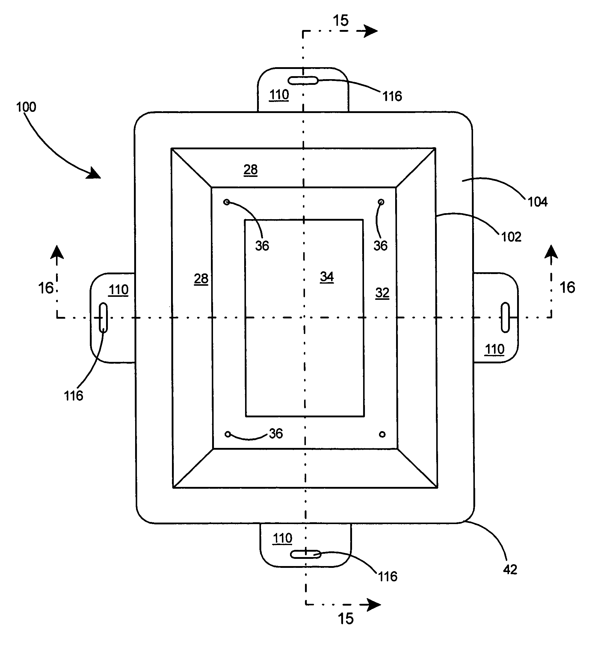
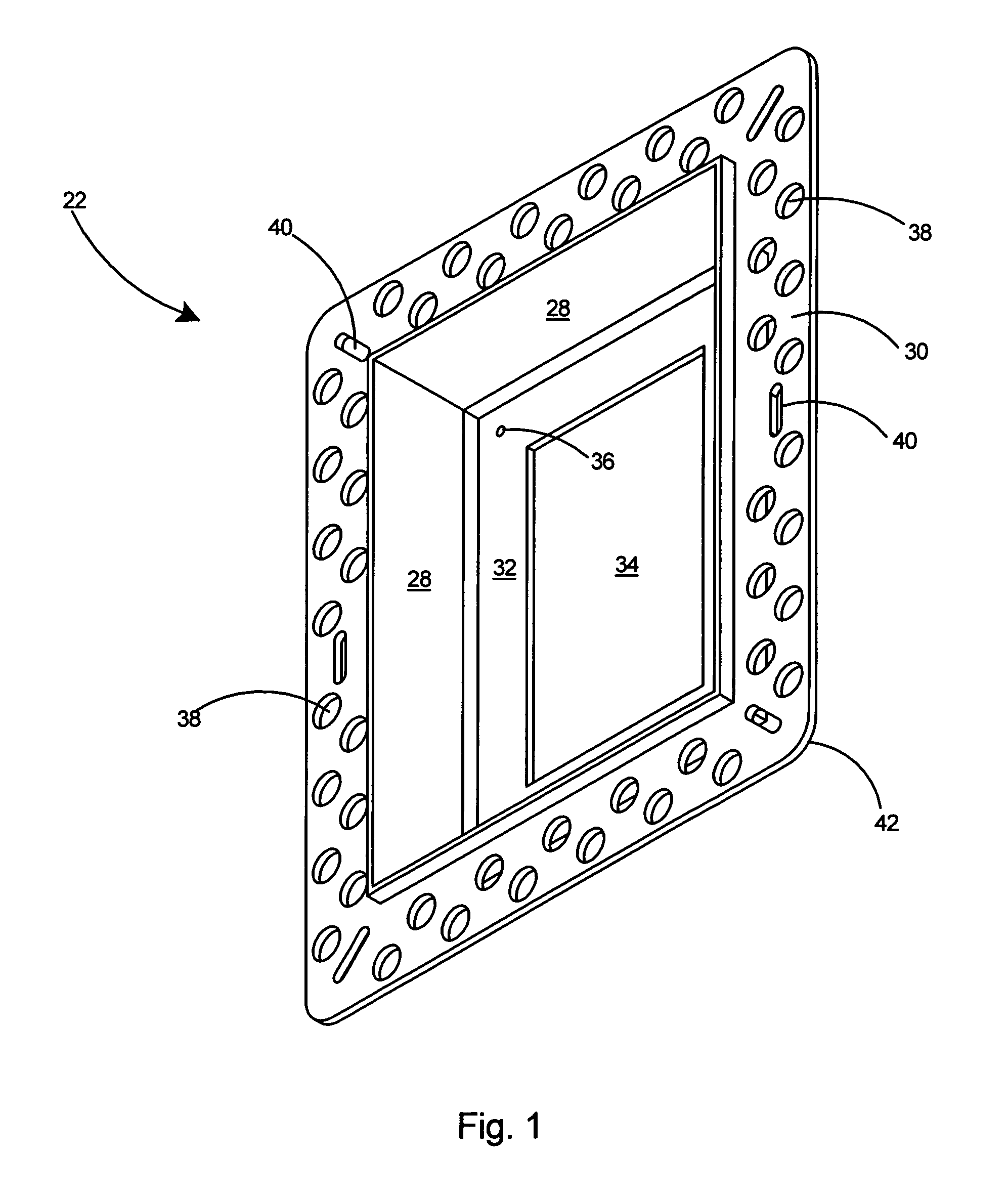
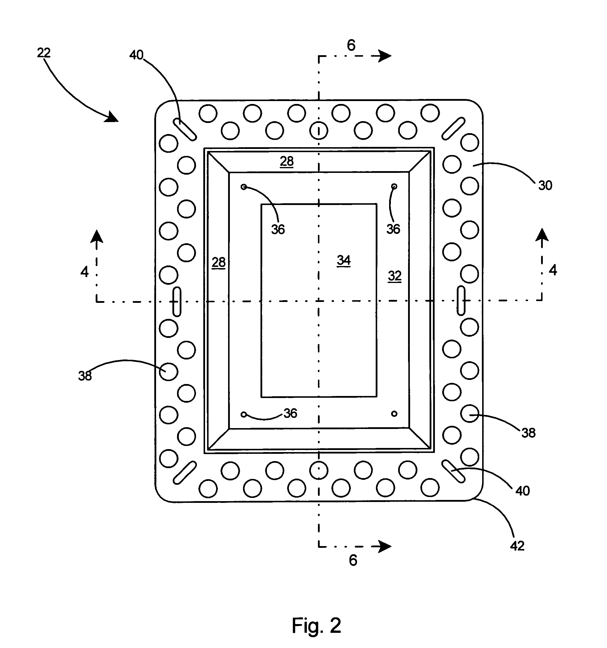
[0035]As shown in FIGS. 1 and 2, the preferred embodiment of the frame member 22 includes sidewalls 28, an outward extending peripheral flange 30, a panel 32, and a central opening 34. Apertures 36 are provided in the panel 32 of the frame member 22. The peripheral flange 30 of the frame member 22 includes a plurality of openings 38 and slots 40 therein. The peripheral flange 30 includes four corners 42 each and a slot 40 in each of the corners.

[0036]Referring...


PUM


Abstract

An electrical box assembly including a frame member and an outlet box assembly with an outlet box and a hinged cover. The frame member includes a peripheral flange and inward sloping sidewalls that extend to a rear panel having a central opening therein. The outlet box includes a flange and a rearward extending sidewall portion. The frame member can be secured to a wall and the rearward extending sidewall of the outlet box inserted into the central opening of the frame member until the flange of the outlet box seats against the rear panel of the frame member. The rear panel of the frame member is recessed a substantial distance from the front edge of the frame member, thereby ensuring that the outlet box assembly and hinged cover in a closed configuration will be recessed within the outer surface of the wall.

Description

FIELD OF THE INVENTION[0001]This invention relates to electrical boxes and specifically to a frame member and outlet box combination for mounting the outlet box and its cover flush with or recessed from the wall of a building.BACKGROUND OF THE INVENTION[0002]Conventional exterior electrical boxes for the mounting of duplex outlets, switches, and other electrical devices are typically installed essentially flush with the wall surface. The exterior electrical boxes usually include a hinged cover to cover the electrical device. Typically the hinged cover extends outward from the front of the electrical box and therefore also extends outward of the wall. Some types of conventional electrical box covers, known as bubble covers, extend a substantial amount from the wall surface.[0003]Outward-extending electrical box and cover assemblies, though they cover the front of the box, are prone to damage by lawnmowers, vehicles, and other hazards as a result of the cover member extending substant...

Claims


Application Information

Patent Timeline
IPC IPC(8): H01H9/02
CPCH02G3/123
Inventor GRETZ, THOMAS J.
Owner ARLINGTON INDS
Why Eureka
Try Eureka