Wavelength cross connect with per port performance characteristics

a cross-connecting and per-port technology, applied in the field of alloptical switching, can solve the problems of high cost of free-space optic solutions, limited wavelength range of serial filter embodiments,

Inactive Publication Date: 2008-01-22
LUMENTUM OPERATIONS LLC
View PDF6 Cites 14 Cited by
  • Summary
  • Abstract
  • Description
  • Claims
  • Application Information

AI Technical Summary

Problems solved by technology

Serial filter embodiments (Fibre Bragg Grating, Thin Film Filters, fibre Mach Zehnder cascade, birefringent filters, etc.) are usually limited in number of wavelength channels due to insertion loss impairments.
Although showing high optical performances, free-space optics solutions are typically expensive, due to extremely tight alignment tolerances of multiple high precision optical elements.
All-integrated embodiments typically make use of thermo-optical switches (see for example C. R. Doerr et al., IEEE Photonics Technology Letters Volume 15, No. 1, January 2003, p 138 to 140), taking up a lot of substrate area and requiring careful heat management, eventually limiting its scalability.
Integrated MEMS-waveguide solutions have also been proposed in the past, but the routing element is usually limited to 1×2 or 2×2, therefore also limiting scalability (M. Katayama et al., Optical Fibre Communication conference, WX4-1, Anaheim, 2001).
However, this usually leads to poor spectral performance, i.e. no wide flat channel shape passband (R. Ryf et al., European Conference on Optical Communications, PD B.1.5, Amsterdam, 2001).

Method used


Image

  • Wavelength cross connect with per port performance characteristics
  • Wavelength cross connect with per port performance characteristics
  • Wavelength cross connect with per port performance characteristics

Examples


Embodiment Construction

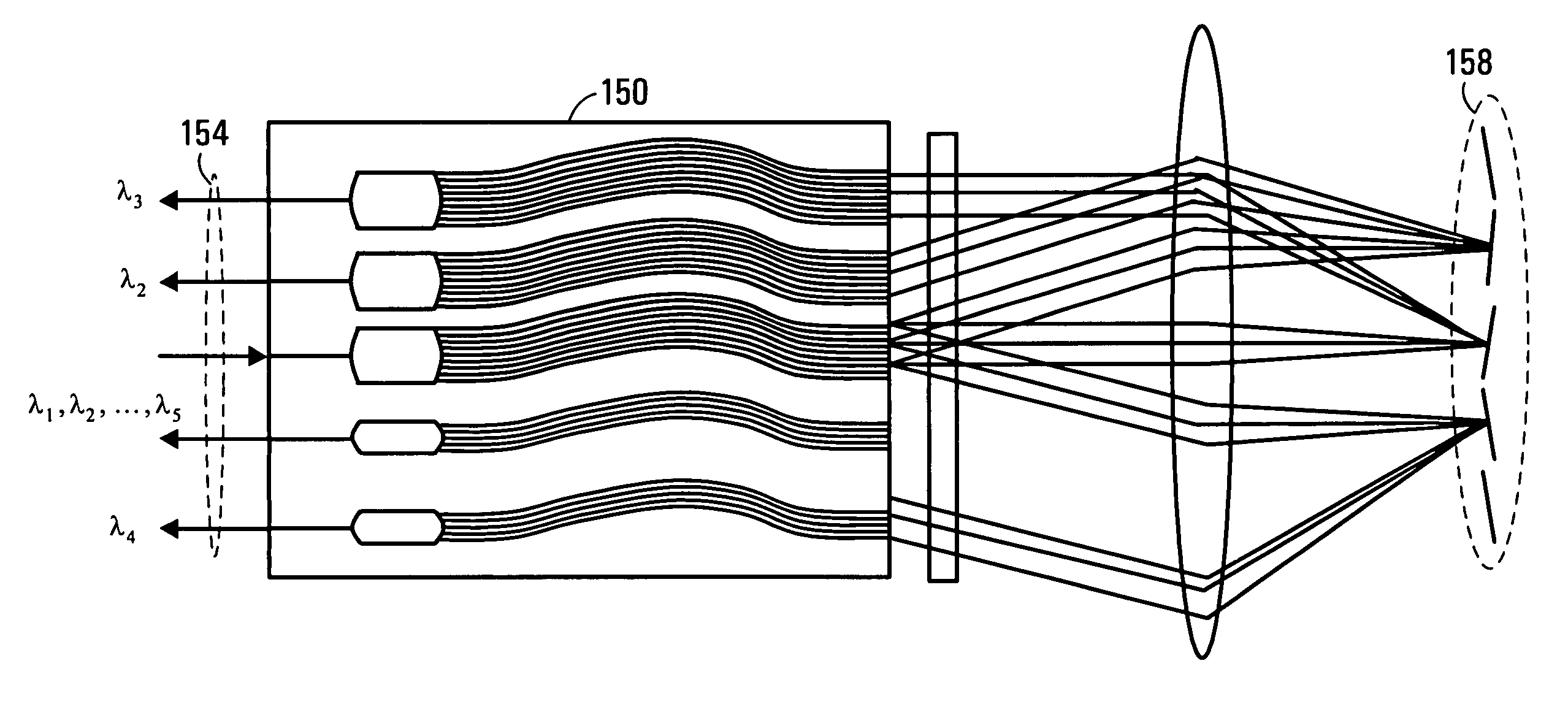
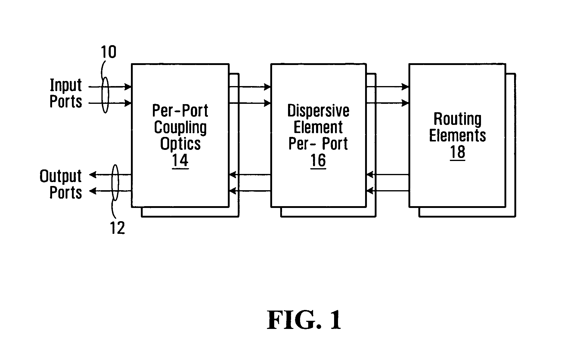
[0045]FIG. 1 is a block diagram of a wavelength cross connect provided by an embodiment of the invention. The arrangement has a set of N input ports 10 (two shown, more generally at least one input port), and a set of M output ports 12 (two shown, more generally at least one output port, with at least two output ports in some embodiments). The ports can be in a single plane, or arranged in two dimensions. Per-port coupling optics are generally indicated at 14. There is a dispersive element per port, generally indicated at 16. Finally, there is a plurality of routing elements generally indicated at 18 for re-directing wavelength signals. If either N or M is equal to one, then the wavelength cross connect is a wavelength selective switch, a wavelength selective switch being a special case of a wavelength cross connect.

[0046]In operation, the port coupling optics 14 functions to couple light between the input and output ports 10,12 and their respective dispersive elements 16. For each ...


PUM


Abstract

A wavelength cross connect is provided in which there is a dispersive arrangement per port for each input port and each output port. Some of the dispersive arrangements have differing characteristics so as to result in different performances at the ports. The dispersive arrangements can differ in the selection of different dispersive elements or differing coupling optics. A particular implementation features a first set of waveguide dispersive elements having first performance characteristics, and a second set of waveguide dispersive elements having second performance characteristics.

Description

RELATED APPLICATIONS[0001]This application claim the benefit of prior U.S. Provisional Application No. 60 / 697,385 filed Jul. 8, 2005 hereby incorporated by reference in its entirety.FIELD OF THE INVENTION[0002]This invention relates to the field of DWDM fibre optics telecommunications and in particular to the field of all-optical switching.BACKGROUND OF THE INVENTION[0003]The advent of DWDM fibre optics telecommunications systems in the early 1990s have enabled a dramatic increase in the transmission capacity over point-to-point communication links. This was achieved through multiplexing of a large number of individually modulated light beams of different wavelengths onto the same optical fibre. Typical systems installed today would have 100 or more independent channels precisely aligned onto an ITU-T standardized grid at 100 GHz, 50 GHz or even narrower channel spacing. With modulation speeds of routinely 10 Gb / s and attaining 40 Gb / s in laboratory experiments, it is not unusual to...

Claims


Application Information

Patent Timeline
Patent Type & Authority Patents(United States)
IPC IPC(8): G02B6/42
CPCG02B6/12011G02B6/12019H04Q11/0005H04Q2011/0024H04Q2011/003H04Q2011/0032H04Q2011/0049
Inventor DUCELLIER, THOMASHNATIW, ALANSEHGAL, PUJARANALLI, ELISEO
Owner LUMENTUM OPERATIONS LLC
Why Eureka
Try Eureka