High efficiency heating, ventilating and air conditioning system

a high-efficiency heating, ventilating and air-conditioning technology, applied in the direction of indirect heat exchangers, heating types, lighting and heating apparatuses, etc., can solve the problems of not describing a high-efficiency heating, ventilating and air-conditioning system that allows maximizing the safety and efficiency of air-conditioning and dehumidification units, and achieves high-efficiency heating, ventilating, and easy and efficient manufacturing and marketing. , the effect of high-efficiency heating

Inactive Publication Date: 2008-03-11
POWERCOLD TECH
View PDF6 Cites 52 Cited by
  • Summary
  • Abstract
  • Description
  • Claims
  • Application Information

AI Technical Summary

Benefits of technology

[0018]It is another object of the present invention to provide a new and improved high efficiency heating, ventilating and air conditioning system which may be easily and efficiently manufactured and marketed.
[0019]It is further object of the present invention to provide a new and improved high efficiency heating, ventilating and air conditioning system which is of durable and reliable constructions.
[0020]An even further object of the present invention is to provide a new and improved high efficiency heating, ventilating and air conditioning system which is susceptible of a low cost of manufacture with regard to both materials and labor, and which accordingly is then susceptible of low prices of sale to the consuming public, thereby making such high efficiency heating, ventilating and air conditioning system economically available.
[0021]Even still another object of the present invention is to provide a high efficiency heating, ventilating and air conditioning system for maximizing the safety and efficiency of air conditioning and dehumidifying units.

Problems solved by technology

While this device fulfills its respective, particular objectives and requirements, the aforementioned patent does not describe a high efficiency heating, ventilating and air conditioning system that allows maximizing the safety and efficiency of air conditioning and dehumidifying units.

Method used


Image

  • High efficiency heating, ventilating and air conditioning system
  • High efficiency heating, ventilating and air conditioning system
  • High efficiency heating, ventilating and air conditioning system

Examples


Embodiment Construction

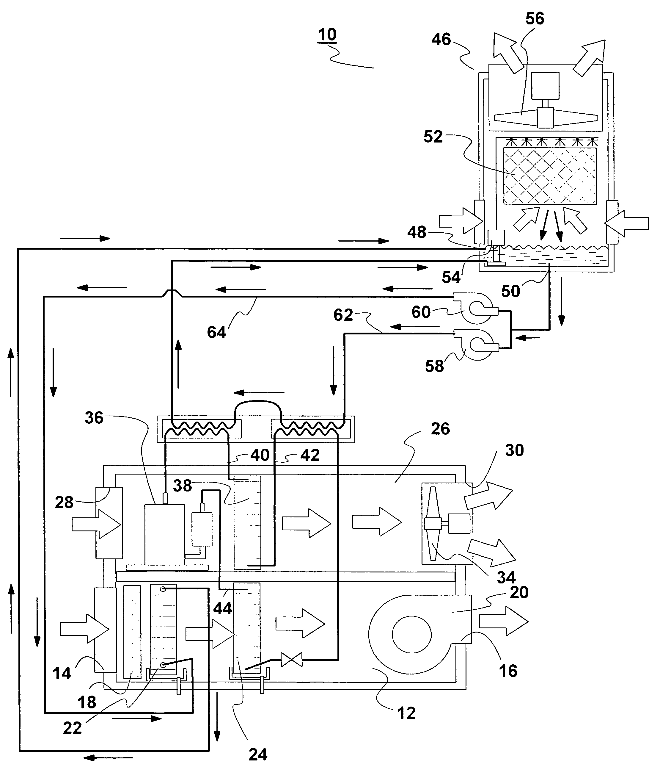
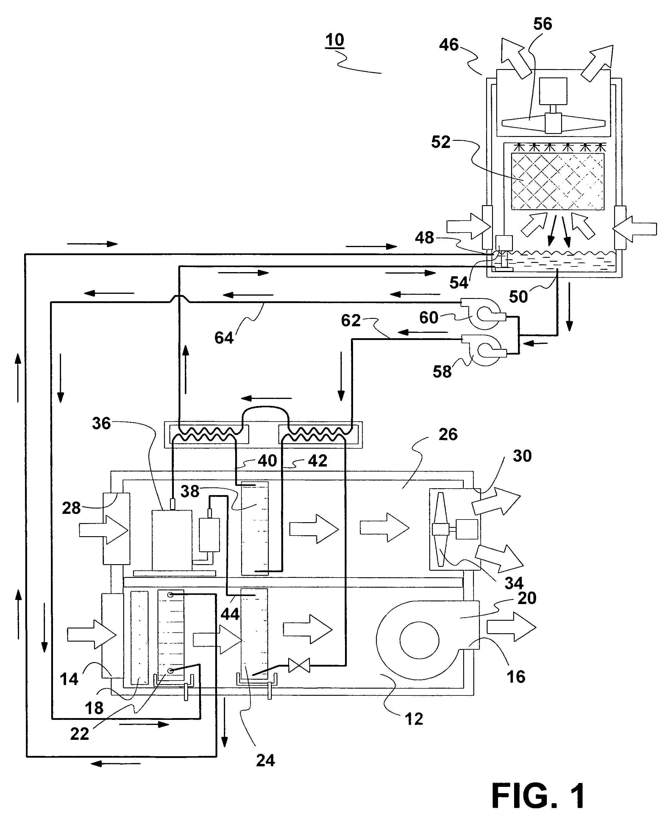
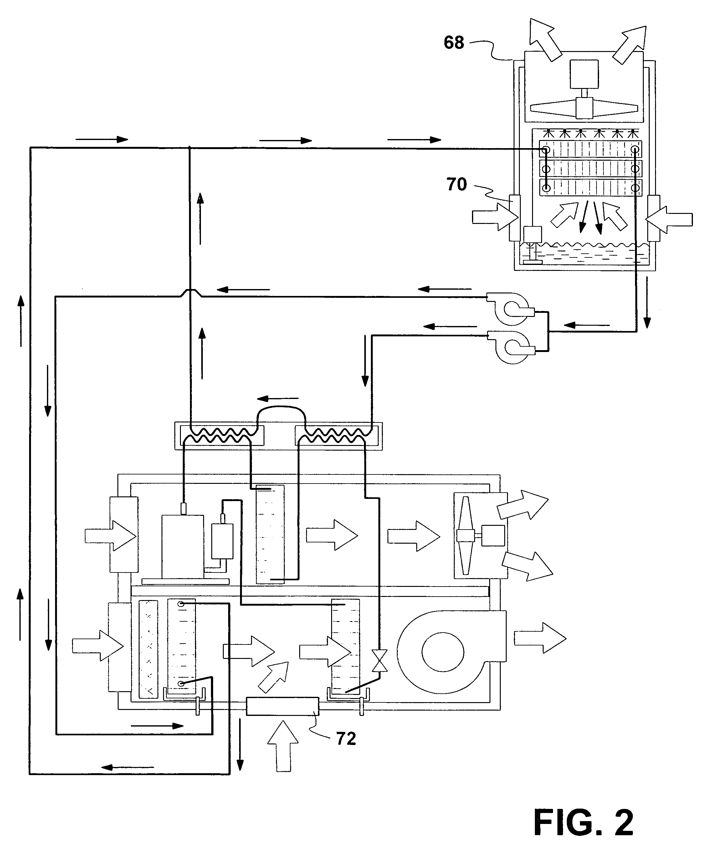
[0029]With reference now to the drawings, and in particular to FIG. 1 thereof, the preferred embodiment, FIG. 2, of the new and improved HVAC, high efficiency heating, ventilating and air conditioning system embodying the principles and concepts of the present invention and generally designated by the reference numeral 10 will be described.

[0030]The present invention, the high efficiency heating, ventilating and air conditioning system 10 is comprised of a plurality of components. Such components in their broadest context include a primary air flow path, a secondary air flow path, and a cooling tower. Such components are individually configured and correlated with respect to each other so as to attain the desired objective.

[0031]First provided is a primary air flow path 12. The primary air flow path has an input end 14. The input end receives air to be conditioned. The primary air flow path has an output end 16. The output end provides cooled air to a space to be cooled. The primary...


PUM


Abstract

A primary air flow path has a pre-cooler and an evaporator. A secondary air flow path includes portions of an air conditioner assembly including a compressor and an condenser. The air conditioner assembly also has lines connecting the compressor and the condenser the evaporator. A cooling tower has a coolant fluid input and output with a heat exchanger section. The heat exchanger section conveys coolant fluid. A pump causes cooling flow of water over the section. The coolant fluid output is adapted to feed a coolant fluid in two coolant fluid paths. The first fluid path is in heat exchanging relationship with the air conditioner assembly. The second fluid pat is coupled to the pre-cooler.

Description

BACKGROUND OF THE INVENTION[0001]1. Field of the Invention[0002]The present invention relates to a high efficiency heating, ventilating and air conditioning system and more particularly pertains to maximizing the safety and efficiency of air conditioning and dehumidifying units.[0003]2. Description of the Prior Art[0004]The use of air conditioning systems of known designs and configurations is known in the prior art. More specifically, air conditioning systems of known designs and configurations previously devised and utilized for the purpose of conditioning air through known methods and apparatuses are known to consist basically of familiar, expected, and obvious structural configurations, notwithstanding the myriad of designs encompassed by the crowded prior art which has been developed for the fulfillment of countless objectives and requirements.[0005]By way of example, U.S. Pat. No. 4,373,346 issued Feb. 15, 1983 to Hebert relates to a Precool / Subcool System and Condenser Theref...

Claims


Application Information

Patent Timeline
Patent Type & Authority Patents(United States)
IPC IPC(8): F25B25/00
CPCF24F3/1423F24F5/0007F24F2203/1016F24F2203/1068F24F2203/1084
Inventor YOHO, SR., ROBERT W.WEBER, RONALD JAMES
Owner POWERCOLD TECH
Why Eureka
Try Eureka