Cable management support bar with strain relief clamps

a technology of cable management and clamping, which is applied in the direction of cables, coupling device connections, insulated conductors, etc., can solve the problem of unfavorable cable strain

Active Publication Date: 2008-03-18
AIMEE E MCVADY PANDUIT CORP
View PDF27 Cites 64 Cited by
  • Summary
  • Abstract
  • Description
  • Claims
  • Application Information

AI Technical Summary

Problems solved by technology

This can result in undesirable strain on the cable where it is terminated to a connector module.

Method used


Image

  • Cable management support bar with strain relief clamps
  • Cable management support bar with strain relief clamps
  • Cable management support bar with strain relief clamps

Examples


Embodiment Construction

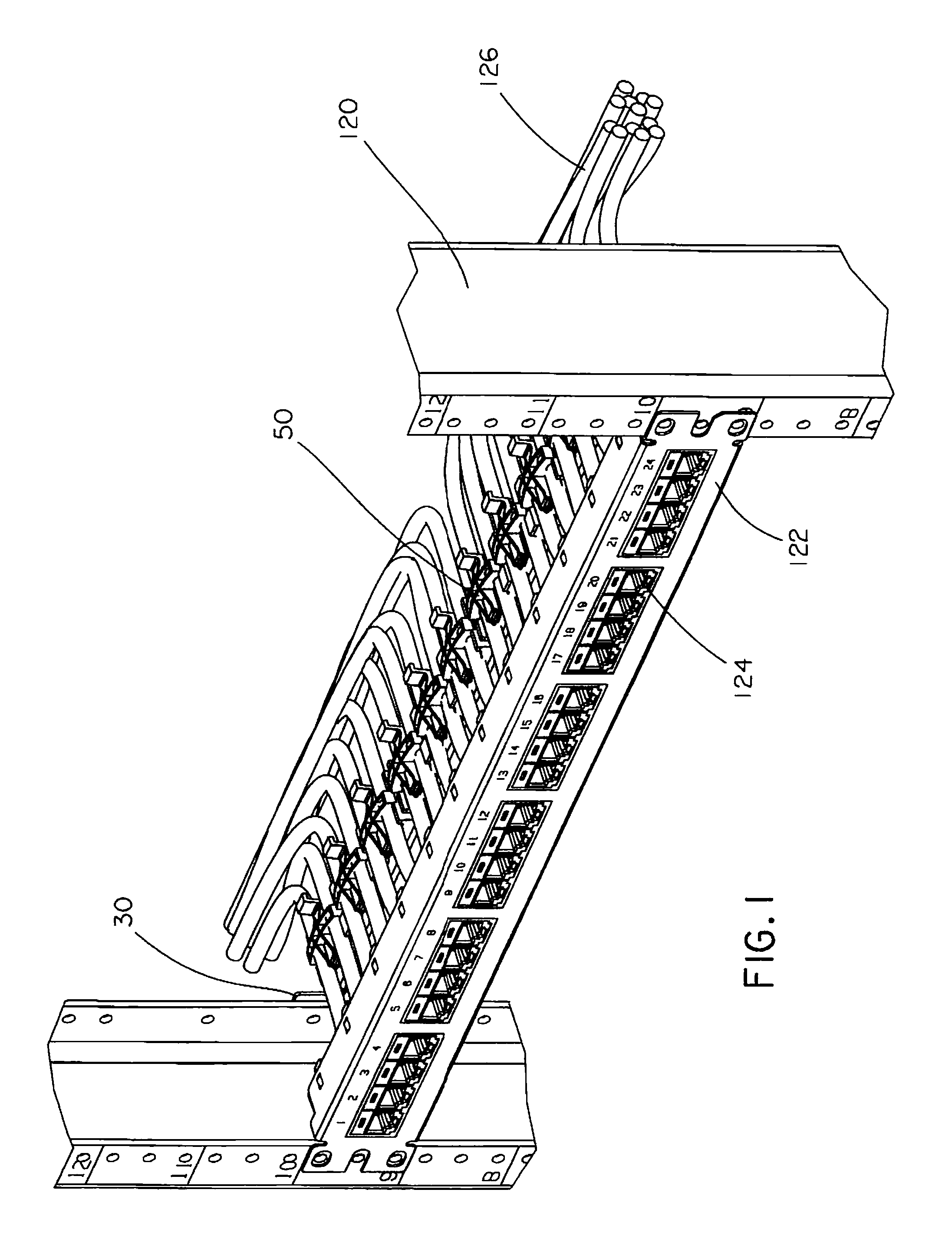
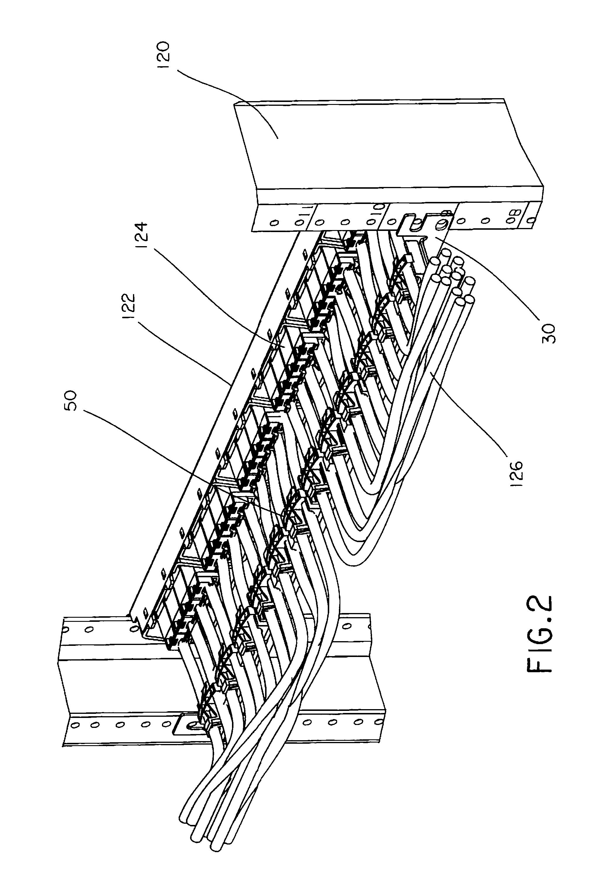
[0031]FIGS. 1 and 2 illustrate an exemplary application of the cable management support bar 30 and strain relief clamps 50 of the present invention. The strain relief clamps 50 are secured to the support bar 30 so that the strain relief clamps 50 are able to guide the cables 126 extending from the network modules 124 installed in the patch panel 122. The strain relief clamps 50 hold the cables 126 in place when the cables are pulled in various directions. Thus, the strain relief clamps 50 support the cables 126 and relieve the strain on the cables 126 as the cables 126 are routed through the rack system.

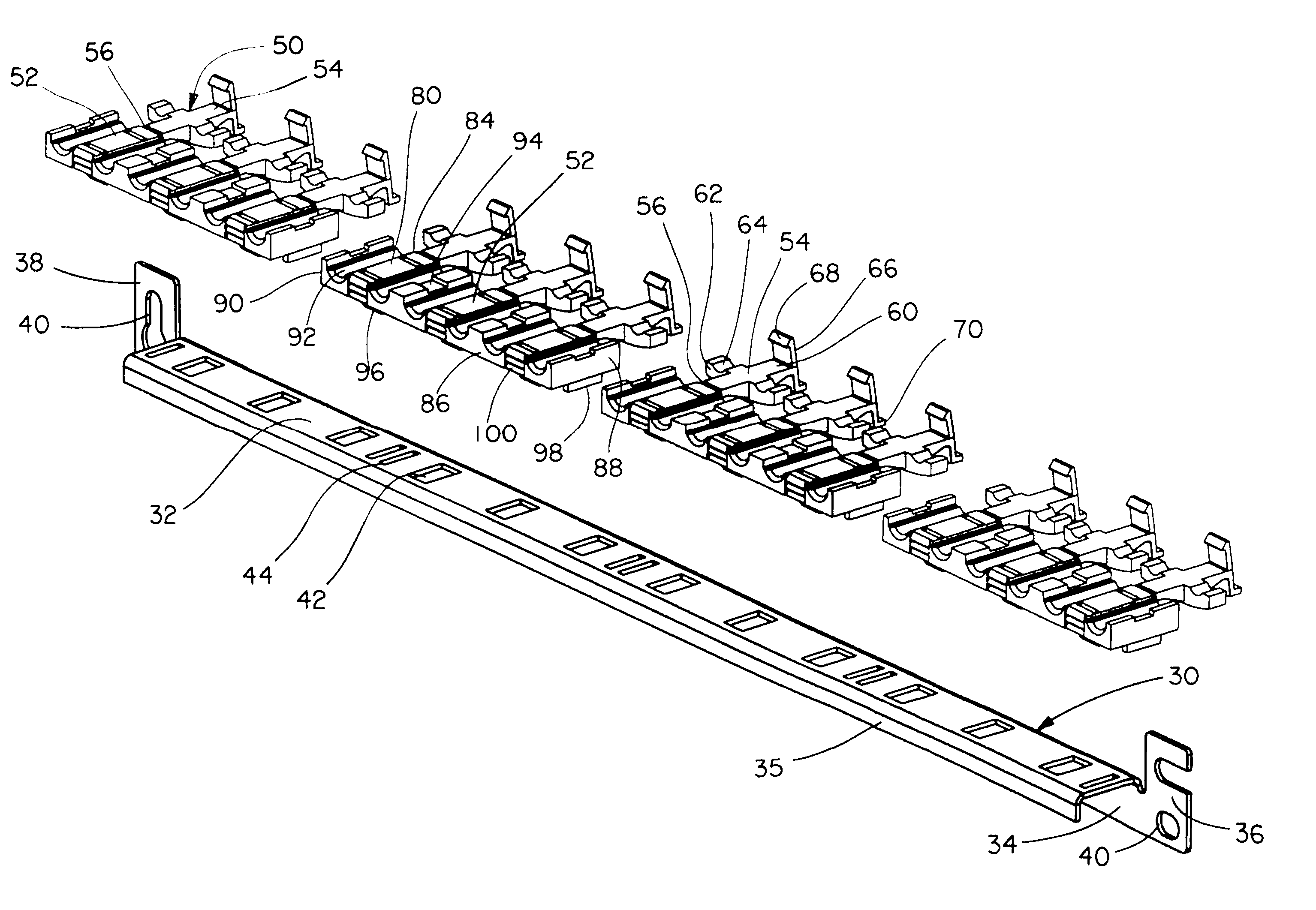
[0032]FIG. 3 illustrates the support bar 30 and the strain relief clamps 50. The support bar 30 includes a horizontal member 32, a vertical member 34, a first end 36 and a second end 38. The first end 36 and the second end 38 have openings 40 for receiving fasteners to secure the support bar 30 to an equipment rack 120. As shown in FIG. 2, each end 36, 38 of the support bar 30 is fas...


PUM


Abstract

A clamp that guides and secures cables in a cable management system. The clamp includes a body member and latch members integrally formed with the body member. The body member includes at least one cable guide and the latch members include outwardly extending arms. The latch members pivot from an open position to a closed position over the body member. When the latch members are in the closed position, each arm is disposed over a cable guide to secure a cable positioned therein.

Description

FIELD OF THE INVENTION[0001]The present invention relates to a cable management system, and more particularly to a cable management support bar with strain relief clamps for holding cables in a cable management system.BACKGROUND OF THE INVENTION[0002]Telecommunication systems include equipment racks or frames to which communication connectors are mounted. The associated cabling is routed through and around the racks to another destination within the rack system or at a device. Either during installation, or at the time of revisions to the system, cables may become intertwined or bent as cables are directed through the system. This can result in undesirable strain on the cable where it is terminated to a connector module. Thus, it is desirable to provide a device that helps guide the cables and provides strain relief on the cables as the cables are directed through the system.SUMMARY OF THE INVENTION[0003]The present invention is directed to a clamp that secures cables in a cable man...

Claims


Application Information

Patent Timeline
Patent Type & Authority Patents(United States)
IPC IPC(8): H02G3/04
CPCH01R9/2416H04Q1/06H04Q1/142H04Q2201/08
Inventor CAVENEY, JACK E.O'YOUNG, JASON
Owner AIMEE E MCVADY PANDUIT CORP
Why Eureka
Try Eureka