Vehicle front end structure

a front end structure and vehicle technology, applied in vehicle maintenance, roofs, vehicle cleaning, etc., can solve the problems of deterioration of the sound reducing effect of the resonator, and achieve the effects of reducing vibrations, reducing vibrations transmitted, and improving the torsional rigidity of the mounting member

Inactive Publication Date: 2008-04-01
DAIKYONISHIKAWA CORP +1
View PDF32 Cites 14 Cited by
  • Summary
  • Abstract
  • Description
  • Claims
  • Application Information

AI Technical Summary

Benefits of technology

[0014]The present invention has been made in view of the above points and its main object is therefore to minimize adverse effects resulting from vibrations of the radiator or the like by contriving the layout in which a liquid storage tank or an intake air resonator is mounted on a resin shroud panel.
[0048]Furthermore, since the mounting member for mounting a radiator or the like to the shroud panel or the like is tightly fitted into the insertion holes of the upper and lower brackets at two vertically spaced points of the mounting member, this provides a stable mounting and the assembly of the mounting member can be carried out easily like the known structure.

Problems solved by technology

Likewise, where the casing for an intake air resonator is provided integrally with the shroud panel as in Document 2, the sound reducing effect of the resonator may be deteriorated because of vibrations of the shroud panel.

Method used


Image

  • Vehicle front end structure
  • Vehicle front end structure
  • Vehicle front end structure

Examples


Embodiment Construction

[0065]A preferred embodiment of the present invention will be described below in detail with reference to the drawings. The following description of the preferred embodiment is merely illustrative in nature and is not intended to limit the scope, applications and use of the invention.

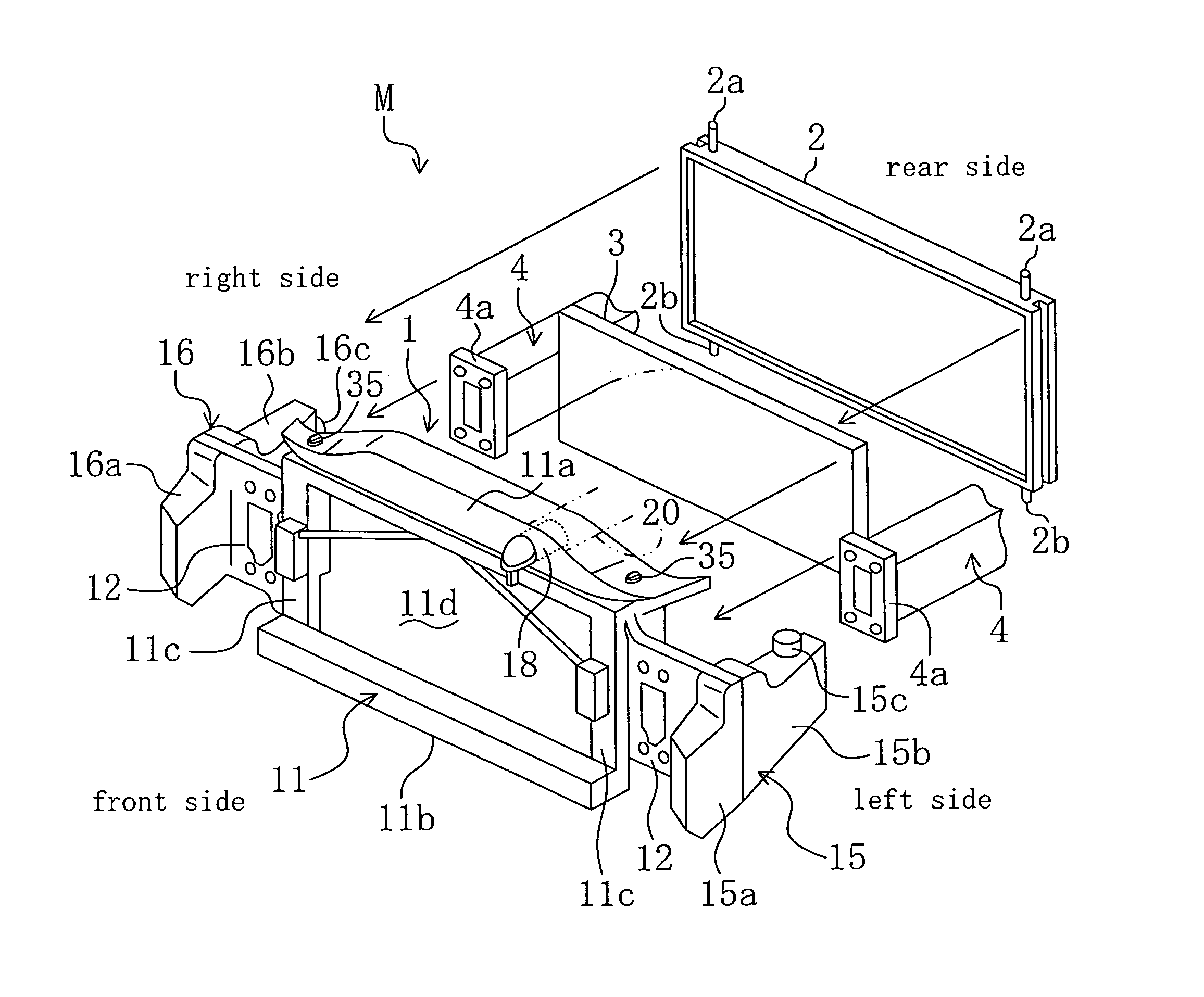
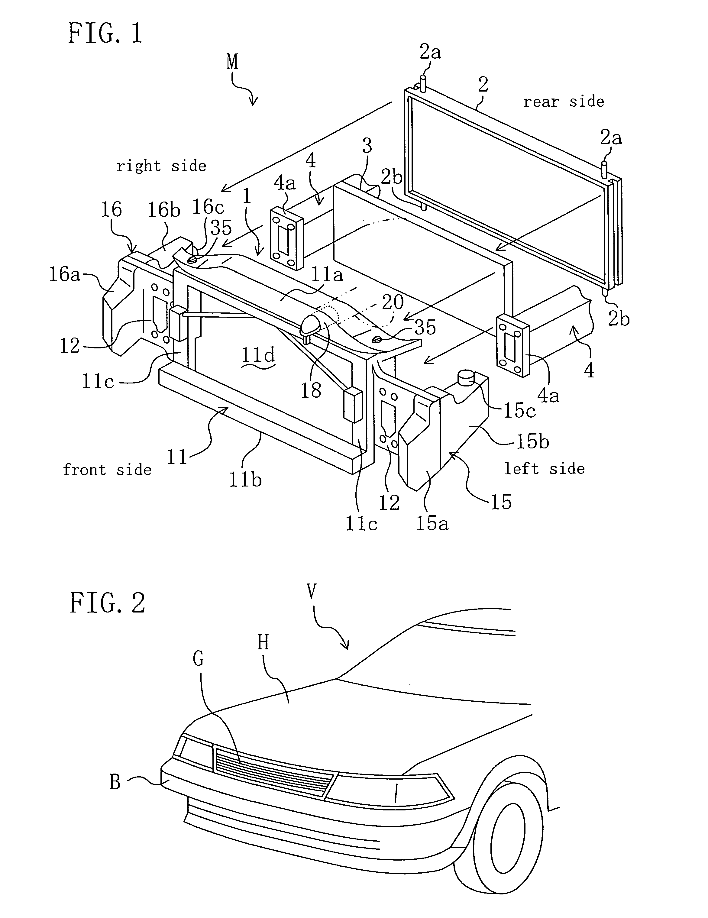
[0066]FIG. 1 is an exploded view of a front end module M of a vehicle to which a structure of the present invention is applied. This module M essentially consists of a resin shroud panel 1 in the form of a substantially rectangular frame, a radiator (heat exchanger) 2 for cooling a cooling water for an unshown engine using wind generated by running of the vehicle, a condenser (heat exchanger) 3 for an air conditioner placed in front of the radiator 2, and a cooling fan (not shown) mounted behind the radiator 2.

[0067]The module M is placed behind (to the back of) a radiator grille G, a front bumper B or the like in the front end of a motorcar / automobile (vehicle) V shown as an example in FIG. 2, with the...


PUM


Abstract

In the case of mounting a liquid storage tank or an intake air resonator on a substantially frame-shaped resin shroud panel (1) with an opening (11d) in which a radiator (2) is disposed, the shroud panel (1) is integrally formed at its both lateral sides with body fastening parts (12, 12) which will be fastened to right and left front side frames (4, 4), respectively, and the body fastening parts (12, 12) are integrally formed on their outsides in the vehicle width direction with casing placement parts (15a, 16a) on which will be placed a casing (15) for a liquid storage tank and a casing (16) for an intake air resonator in proximity to the body fastening parts (12, 12), respectively.

Description

CROSS-REFERENCES TO RELATED APPLICATIONS[0001]This application claims priority under 35 USC 119 to Japanese Patent Applications Nos. 2004-177927, 2004-177931 and 2004-178270, all filed on Jun. 16, 2004, the entire contents of which are incorporated herein by reference.BACKGROUND OF THE INVENTION[0002](a) Field of the Invention[0003]This invention relates to a front end structure for a vehicle.[0004](b) Description of the Related Art[0005]An example of known vehicle front end structures is disclosed in Japanese Unexamined Patent Publication No. H11-171041 (hereinafter, referred to as Document 1). With this vehicle front end structure, a resin shroud panel is previously formed with mounting parts for vehicle components such as a radiator, a condenser and a cooling fan, these vehicle components are subassembled on the shroud panel to form a module and the module is then assembled on a vehicle body, e.g., front side frames. Since subassembled components are assembled as a module on the ...

Claims


Application Information

Patent Timeline
Patent Type & Authority Patents(United States)
IPC IPC(8): B60K11/04B62D25/08
CPCB60K11/04B62D25/084
Inventor UDO, TADASHIKONDOU, KAZUMAOGAWA, MASANORINAGANO, NAOKIOHHIRA, TAKAHIDETAKAHASHI, KUNIO
Owner DAIKYONISHIKAWA CORP
Why Eureka
Try Eureka