Method for mounting shielding on a turbine casing, and mounting assembly for implementing same

a technology for turbine casings and mounting assemblies, which is applied in the direction of liquid fuel engines, forging/pressing/hammering apparatuses, combustion-air/fuel-air treatment, etc., can solve the problems of limiting the life of shielding flanges, progressive breaking away from fasteners, and reducing the shielding mass. , to achieve the effect of simplifying the mounting and minimizing the shielding mass

Active Publication Date: 2016-08-30
SAFRAN HELICOPTER ENGINES
View PDF15 Cites 5 Cited by
  • Summary
  • Abstract
  • Description
  • Claims
  • Application Information

AI Technical Summary

Benefits of technology

[0010]The invention aims at overcoming the disadvantages of the above described technologies and, in particular, getting rid of the thermal inertia of the shielding acting on the mechan...

Problems solved by technology

But it seems that the lifetime of such shielding flanges may be strongly limited.
However, such an environment may limit the shield retaining capacities, which will then require more consequent thicknesses.
Such a...

Method used


Image

  • Method for mounting shielding on a turbine casing, and mounting assembly for implementing same
  • Method for mounting shielding on a turbine casing, and mounting assembly for implementing same
  • Method for mounting shielding on a turbine casing, and mounting assembly for implementing same

Examples


Embodiment Construction

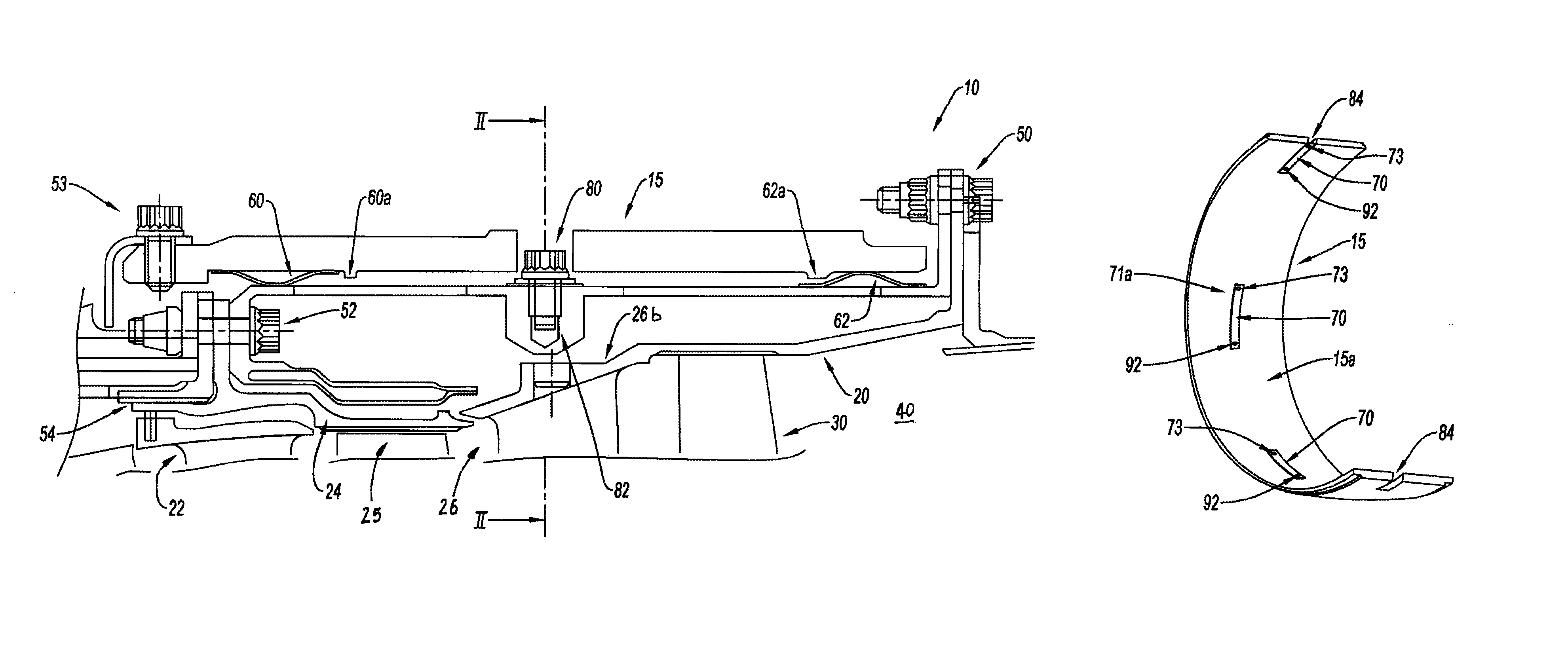
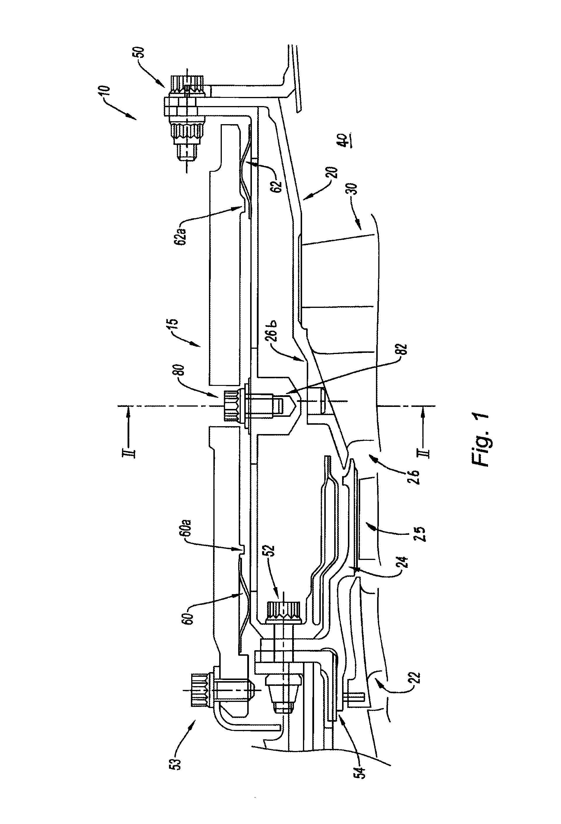
[0030]Referring to the partial sectional view of FIG. 1, the free turbine 10 comprises in particular an external shield 15 and a casing 20 forming the main structure of the engine and to which the air vein forming elements are to be connected: the turbine distributors 22 and 26, the turbine rings 24 and 26b and the turbine wheels 25 and 30 through a bearing structure (not shown). Each blade system is made of a stationary vane system or air flux “distributor” stator followed—in the direction of the air flows—by a mobile blade or wheel system, and of an outlet vein 40 to get access to the nozzles (not shown).

[0031]The different seals are provided by flanges or joints 50, 52 and 54 between different parts being adjacent to the casing 20 itself in connection with the shield 15.

[0032]Furthermore, two spring blades 60 and 62 made of a metal sheet are provided between the shield 15 and the casing 20 so as to dampen the vibrations, for example upon thermo-mechanical transitions. Such blades...


PUM

PropertyMeasurementUnit
Mechanical strengthaaaaaaaaaa
Flexibilityaaaaaaaaaa
Mechanical propertiesaaaaaaaaaa

Abstract

A method and structure negating thermal inertia of a solid portion, such as shielding, which influences mechanical behavior of parts of an engine structure, by reducing forces transmitted to the engine structure during an event in which a turbine blade ruptures, while preserving mechanical strength and vibratory positioning. The structure includes a flexible fastener for a shield, enabling producing a fusible section. An assembly for mounting a shielding onto a casing of the engine structure of a turbine includes connection lugs and points for attachment to the casing and shielding. The attachment points are sufficiently spaced apart in accordance with curvature of the shielding and casing so connection between the lugs and the shielding or casing, and connection of the attachment points, are substantially tangential. The lugs are sized so the connection has sufficient flexibility to control vibratory positioning thereof and ensure sufficient mechanical strength under thermo-mechanical loads.

Description

BACKGROUND OF THE INVENTION[0001]1. Field of the Invention[0002]The invention relates to a shield mounting method on a turbine casing of an engine structure, in particular a turbine mounted on an aircraft or a land industrial turbine, as well as a mounting assembly for implementing such a method.[0003]2. Description of the Related Art[0004]The field of the invention is more particularly the protection of engines, especially for power turbines, such as turbo-engines of aircrafts. The engine structure requires the presence of a protection shield to confine any part or element being able to break away from the engine structure or the casing. In particular, the shielding of a free turbine provides the retention of all free turbine blades upon an event of the “blade-shedding” type in case of overspeed. Indeed, the blades are built to break in a given speed range so as to guarantee the operation capacity of the engine under a given threshold and guarantee the integrity of the disks beyond...

Claims


Application Information

Patent Timeline
IPC IPC(8): F01D25/24F01D21/04F02K1/82F04D27/00F04D29/52B21K1/26F04D27/02F02C7/05
CPCF01D21/045F01D25/24F02C7/05F02K1/82F04D27/008F04D29/522F04D29/526B21K1/26F04D27/0261F05D2240/14Y10T29/49323Y02B30/70F01D21/04F01D25/26
Inventor SAHORES, JEAN-LUC PIERREJAUREGUIBERRY, CAROLECASAUX-BIC, JEAN-MAURICEDESCUBES, OLIVIER PIERRE
Owner SAFRAN HELICOPTER ENGINES
Why Eureka
Try Eureka