Method and device for steering vehicle having no contact with track

a technology of non-contact steering and vehicle, which is applied in the direction of vehicle position/course/altitude control, process and machine control, instruments, etc., can solve the problems of not being able to carry out a control corresponding to a run situation, not being able to meet the requirements of a vehicle in an airport, and reducing the cost of facilities, so as to improve comfort and improve control performance. , the effect of improving the degree of comfor

Active Publication Date: 2010-07-20
MITSUBISHI HEAVY IND ENG LTD
View PDF25 Cites 5 Cited by
  • Summary
  • Abstract
  • Description
  • Claims
  • Application Information

AI Technical Summary

Benefits of technology

[0007]Another object of the present invention is to provide a steering apparatus for a rail non-contact vehicle and a steering method for the same, in which a smooth operation can be accomplished by taking a future (predicted) variable into a control system.
[0009]Also, it is an object of the present invention to provide a steering apparatus for a rail non-contact vehicle and a steering method for the same, in which improvement in automatic control performance can be attained as well as improvement in a degree of comfort.
[0018]Also, the control section may further include an optimization calculating section configured to optimize a control data, and the optimization calculating section minimizes vibration resulting from the steering of the vehicle. In this case, when m and n take an optional one of a plurality of combinations of m and n, a deviation between a position of the vehicle main body at an m-th run and an n-th run on the target route is expressed as an amplitude. The optimization calculating section determines the correction steering angle such that a square of the amplitudes is minimized. Also, when m and n take an optional one of a plurality of combinations of m and n, an acceleration of the vehicle main body between the m-th run and the n-th run on the target route is expressed. The optimization calculating section determines the correction steering angle such that squares of the accelerations are minimized.
[0031]The steering apparatus for a rail non-contact vehicle and the steering method thereof according to the present invention establishes a technique of automatic operation of a new transportation system, and dramatically improves smooth control performance, and thereby remarkably improves a degree of comfort. The steering apparatus mechanism using the ball screw axis reduces cost, simplifies the mechanism, and dramatically improves smooth control performance.

Problems solved by technology

The rubber tire type vehicle has a great degree of freedom on a running direction, and is not suitable for a vehicle in an airport.
Securing the strength hinders desired reduction in facilities cost.
If the table value is fixed, it become difficult to carry out a control corresponding to a run situation that changes from moment to moment.
Therefore, conventionally, a rapid velocity change resulted from a rapid change in a steering angle (for example, acceleration in a direction perpendicular to a rail direction) is caused, thereby, leading to aggravation of degree of comfort.

Method used


Image

  • Method and device for steering vehicle having no contact with track
  • Method and device for steering vehicle having no contact with track
  • Method and device for steering vehicle having no contact with track

Examples


first embodiment

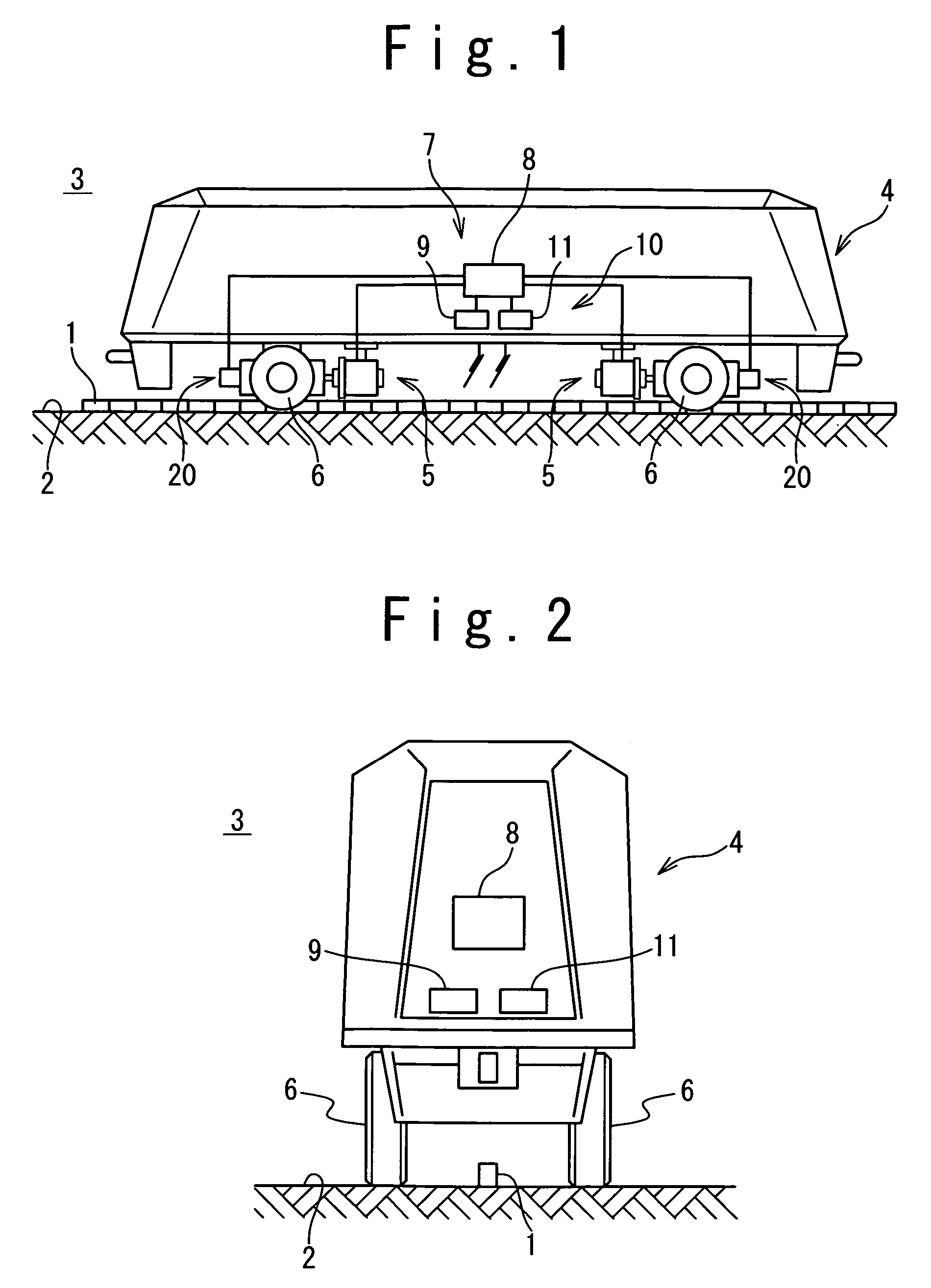
[0055]FIG. 1 is a diagram showing the steering apparatus of the rail non-contact vehicle according to the present invention. Referring to FIG. 1, a guide line 1 is provided on a dedicated rail plane 2 to define a rail reference. The dedicated rail plane 2 is formed linearly or curvedly. The guide line 1 is shown in FIG. 1 such that it projects from the rail plane 2. However, the guide line 1 may be formed to be embedded in the rail plane 2. The vehicle 3 is provided with a vehicle main body 4 and a cart 5. The cart 5 is supported by the dedicated rail plane 2. The vehicle main body 4 is supported on the rail plane 2 by the cart 5 in such a manner that the vehicle main body 4 can turn freely around a perpendicular axis or an axis normal to the rail plane. The cart 5 is provided with wheels 6.

[0056]The steering system is provided with a control section 10 as a non-mechanical steering system section, and a drive section 20 as a mechanical steering system section. The steering system is...

second embodiment

The deviation ΔW is processed similarly to the position deviation ΔD shown in the second embodiment, such that the absolute value of deviation ΔW (=W2−W1) becomes small.

[0091]Referring to FIG. 16, the deviation detection method according to the fifth embodiment of the present invention will be described. Referring to FIG. 16, safe guide rings 53 are added to the vehicle 3 of the FIG. 12 in the fifth embodiment of the present invention. The safe guide ring 53 is provided on either side of the main body of the vehicle 3 or the cart 5. A rotation shaft 54 of the safe guide ring 53 is parallel to the opposing surface of the curbstone 43 on either side. The safe guide ring 53 does not contact the curbstone 43. In this case, the construction cost of the safe guide ring 53 which does not contact the curbstone 43 is significantly lower compared with the construction cost of the well-known guide rail for guide rails. There is no noise generated between the curbstone 43 and the safe guide rin...

seventh embodiment

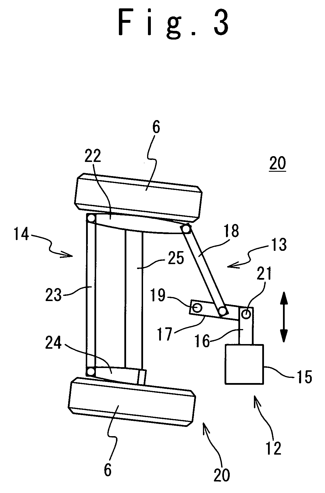
[0094]Referring to FIG. 18, the drive section 20 of the steering system used in the steering apparatus of the rail non-contact vehicle according to the present invention will be described. Referring to FIG. 18, the present embodiment realizes the above-mentioned real time high precision route control and the safety associated with the control. The feature is achieved by using a ball screw and a safety bar, and adding a safe clutch.

[0095]The drive section 20 is provided with the actuator 12, the first link mechanism 13, and the second link mechanism 14. An actuator fixed section 55 fixedly supported by the cart 5 is equivalent to the above-mentioned actuator main body 15. An actuator movable section 56 which moves forward and backward to the actuator fixed section 55 is equivalent to the above-mentioned piston rod 16. A nut 57 is fixed to the actuator fixed section 55. A ball screw 58 screwed in the nut 57 is rotatably supported by bearings 60 and 61 which are fixed to the actuator m...


PUM


Abstract

A rail non-contact vehicle includes wheels, a vehicle main body supported by the wheels, and a steering control system. The steering control system includes a control section configured to control a steering of the wheels in a non-mechanical manner, and a drive section configured to mechanically drive the steering of the wheels. The control section includes a first detector configured to detect 1-dimensional coordinate data of a target route, a steering angle holding section configured to hold a target steering angle corresponding to the 1-dimensional coordinate data, a second detector configured to detect a current deviation between the target route and a current position of the vehicle main body, and a control steering angle calculating section configured to generate a control steering angle corresponding to the current deviation and the target steering angle.

Description

[0001]This application is a 371 of PCT / JP03 / 13953, filed Oct. 30, 2003, which claims priority under 35 U.S.C. §119(a)-(e) of Japanese Application 2002-316559, filed Oct. 30, 2002.TECHNICAL FIELD[0002]The present invention relates to a steering apparatus for a rail non-contact vehicle and a steering method for the same, and more particularly to a steering apparatus for a rail non-contact vehicle, in which a steering operation is automated, and a steering method for the same.BACKGROUND ART[0003]Adoption of a new transportation system is now promoted in narrow areas such as an airport and an exhibition site. Unlike Shinkansen bullet train as wide area transportation technology, the new transportation system is not required to transport in high speed and to carry out mass transportation, but is required not to need a large-scaled rail facility. As a vehicle, which needs no rail facilities, a rubber tire type vehicle such as an automobile and a bus is known in Japanese Patent Laid Open A...

Claims


Application Information

Patent Timeline
Patent Type & Authority Patents(United States)
IPC IPC(8): B61J3/00B62D1/26B62D1/28G05D1/02
CPCB62D1/265G05D1/0246B62D1/28G05D1/0234G05D2201/0216G05D1/02
Inventor KONO, HIROYUKIYAMAGUCHI, MASAHIROYAMASHITA, HIROSHIMASUKAWA, MASAHISAMORHICHIKA, SHUNJIMOCHIDOME, HIROYUKIFUKUDA, KOKI
Owner MITSUBISHI HEAVY IND ENG LTD
Why Eureka
Try Eureka