Visual wear indicator for footwear

a technology of visual wear indicators and footwear, applied in the direction of instruments, force/torque/work measurement apparatus, analysis using chemical indicators, etc., can solve the problems of increased stress on regions, increased pressure on visual wear indicators during activity,

Inactive Publication Date: 2008-04-08
SANGUINETTI CHERI
View PDF20 Cites 58 Cited by
  • Summary
  • Abstract
  • Description
  • Claims
  • Application Information

AI Technical Summary

Benefits of technology

[0011]Thus, in new or relatively new shoes, the adjacent regions may remain distinct from each other. However, as the midsole begins to loose its cushioning and / or the outer sole begins to wear down, the stress on regions will increase and eventually the regions will mix. As the regions are different colors, the blending of the boundary between the regions will be visually evident and give a quick and easy read on how worn the shoe is.

Problems solved by technology

However, over time, as the midsole and / or outer sole of the shoe wear away, the pressure exerted on the visual wear indicator increases during activity.
However, as the midsole begins to loose its cushioning and / or the outer sole begins to wear down, the stress on regions will increase and eventually the regions will mix.

Method used


Image

  • Visual wear indicator for footwear
  • Visual wear indicator for footwear
  • Visual wear indicator for footwear

Examples


Embodiment Construction

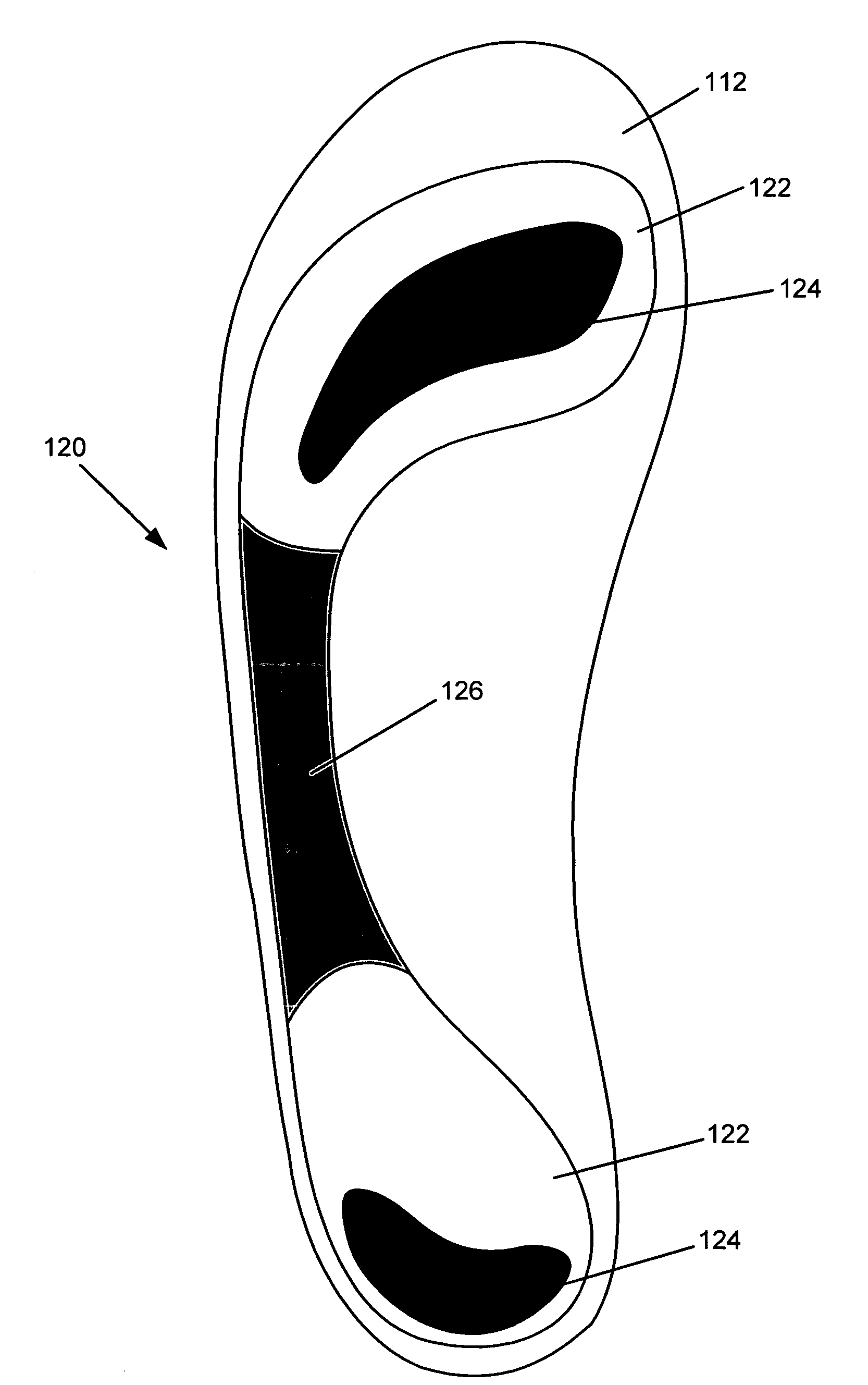
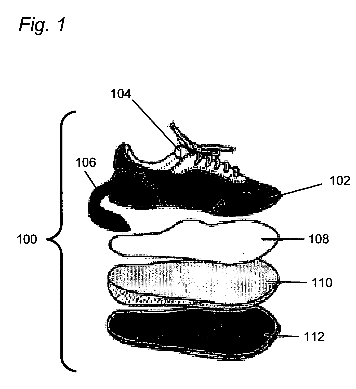
[0025]Embodiments will now be described with reference to FIGS. 1 through 14, which relate to a visual wear indicator which may be used for example in footwear. As explained hereinafter, the visual wear indicator may be used in other articles, including for example in seats such as bicycle saddles and protective gear such as helmets. Moreover, while the present invention is explained hereinafter with respect to athletic shoes, the present invention may used in a wide variety of other footwear.

[0026]It is understood that the present invention may be embodied in many different forms and should not be construed as being limited to the embodiments set forth herein. Rather, these embodiments are provided so that this disclosure will be thorough and complete and will fully convey the invention to those skilled in the art. Indeed, the invention is intended to cover alternatives, modifications and equivalents of these embodiments, which are included within the scope and spirit of the invent...


PUM


Abstract

A visual wear indicator is disclosed capable of giving a visual indication of the degree of wear on an athletic or other type of shoe. In general, the visual wear indicator may operate by having two different colored regions, each having a viscosity which varies a function of pressure. Before pressure is applied, the boundary between the two regions is clear. However, over time, as the midsole and / or outer sole of the shoe wear away, the pressure exerted on the visual wear indicator increases during activity. As the pressure increases, the viscosity of the regions eventually decreases. When the viscosity decreases, the regions bleed together, and the boundary between the regions becomes less clear. The degree of mixture between the regions may be calibrated to give a clear visual indication of when the shoe has worn down to the point where the shoe is unable to provide a desired level of support and stress absorption.

Description

BACKGROUND OF THE INVENTION[0001]1. Field of the Invention[0002]Embodiments of the present invention relate to a visual wear indicator for indicating wear in footwear and other articles.[0003]2. Description of the Related Art[0004]Footwear for athletics is a multi-billion dollar industry. Vast amounts of resources are spent developing footwear that is compatible with the biomechanics of the foot, leg and back so that the shoes absorb much of the stress exerted on the body during athletic activity. As different athletic activities exert different stresses on the body, most athletic activities now have footwear that has been specifically designed for that activity.[0005]When new, contemporary athletic shoes are effective in reducing stress on the body. However, athletic shoes tend to wear down over time with normal usage. For example, the constant impact and shear forces on the bottom outer sole against the athletic surface tends to wear away the outer sole. Moreover, the forces exert...

Claims


Application Information

Patent Timeline
Patent Type & Authority Patents(United States)
IPC IPC(8): G01D13/00A43B13/00
CPCA43B1/0027A43B13/026A43B13/12A43B13/188A43B13/189G01D7/005
Inventor SANGUINETTI, CHERI
Owner SANGUINETTI CHERI
Why Eureka
Try Eureka