
Plug locking assembly

a technology of locking assembly and plug, which is applied in the direction of coupling device connection, coupling contact member, securing/insulating coupling parts, etc., can solve the problem of unauthorized removal of modular plugs from their corresponding jacks, and achieve the effect of preventing the plug from being withdrawn

Inactive Publication Date: 2008-04-08
PANDUIT
View PDF17 Cites 164 Cited by
  • Summary
  • Abstract
  • Description
  • Claims
  • Application Information

AI Technical Summary

Benefits of technology

Effectively prevents tampering and unintended removal of plugs by securing them within the jack, while allowing controlled removal using a specialized tool, enhancing security and reliability in modular connections.

Problems solved by technology

Because these tabs are readily accessible by fingernails and / or small tools, the unauthorized removal of modular plugs from their corresponding jacks is a common problem.

Method used


Image

  • Plug locking assembly
  • Plug locking assembly
  • Plug locking assembly

Examples


Embodiment Construction

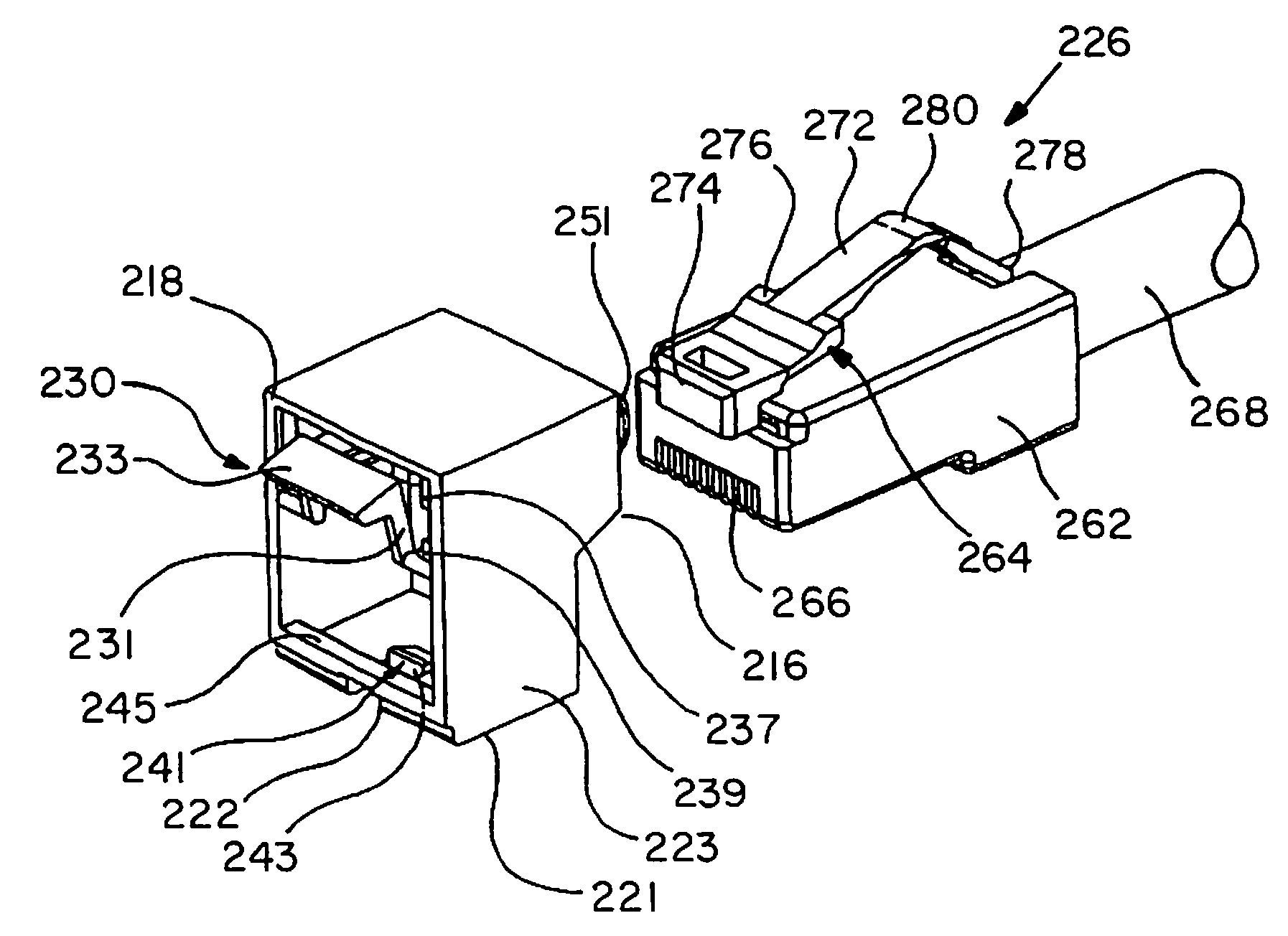
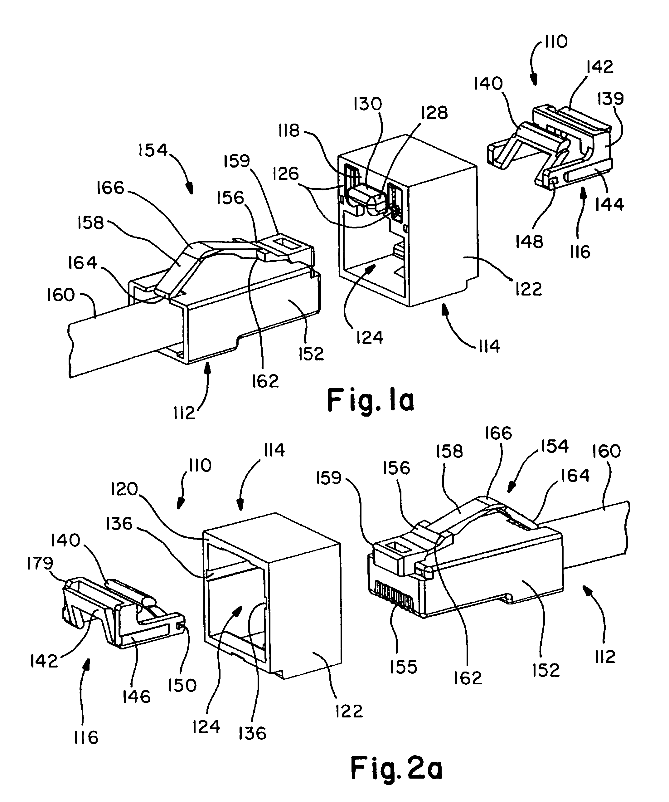
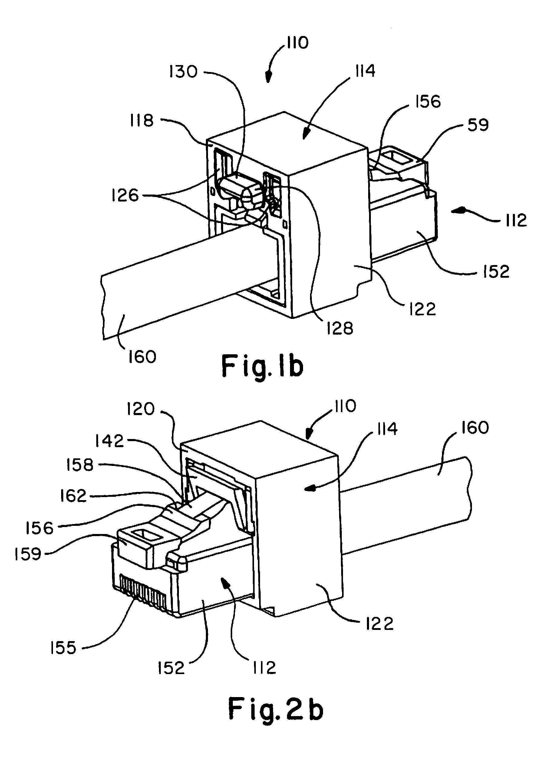
[0058]Referring now to FIGS. 1A-2C, one embodiment of the plug locking assembly 110 of the present invention is shown. Locking assembly 110 comprises housing 114 and pre-assembled locking clip 116.

[0059]Housing 114 comprises front 118, rear 120 and sidewalls 122, defining open space or center 124 therebetween for receiving plug 112. Front 118 may include two or more access windows 126 which, as shown in FIGS. 1A and 1B, exhibit a rectangular shape. It is likewise contemplated that windows 126 may be formed from various other shapes. Front 118 may further include tab 128, integrally formed with housing 114. Tab 128 comprises top portion 130, sidewalls 132 and downwardly facing hook 134, shown in FIGS. 10 and 11A. Internal portions of sidewalls 122 of housing 114 may comprise longitudinal grooves 136, as seen in FIGS. 3 and 4. Housing 114 is typically dimensioned Such that at least a portion of plug 112 extends beyond open center 124, with plug 112 engaged within housing 114, as seen ...


PUM


Abstract

A plug locking assembly comprises a housing comprising a top surface, a bottom surface and opposing sidewalls defining an open space therebetween, the open space for receiving and carrying a plug comprising a spring member. The plug locking assembly is adapted to prevent unwanted access to modular plugs engaged in associated jacks. In one embodiment, the plug locking assembly comprises a plug protection member comprising a surface spaced apart from the open space and positioned to overlie at least a portion of the spring member with the plug engaged within the housing. The plug locking assembly may further comprise a locking clip releasably securable within the housing.

Description

FIELD OF INVENTION [0001]The present invention relates to a plug locking assembly and, more particularly, to a plug locking assembly for preventing unwanted access to a plug positioned within an associated jack.BACKGROUND [0002]Modern telecommunication and data processing equipment often includes modular plugs that engage jacks or receptacles to create electrical connections. Typical modular plugs include an integral resilient spring or latch mechanism for releasably securing the plug within the jack. In most cases, the springs or latches comprise a tab that projects out of the receptacle after insertion. Because these tabs are readily accessible by fingernails and / or small tools, the unauthorized removal of modular plugs from their corresponding jacks is a common problem.[0003]There is a need, therefore, for a plug locking assembly that protects modular plugs and prevents their unintended disconnection from associated jacks.SUMMARY OF THE INVENTION [0004]The present invention relat...

Claims


Application Information

Patent Timeline
Patent Type & Authority Patents(United States)
IPC IPC(8): H01R4/50
CPCH01R13/6397H01R24/64
Inventor CAVENEY, JACK E.BROUWER, SHAUN P.
Owner PANDUIT
Learn More