System and method for a minimized antenna apparatus with selectable elements

a technology of selectable elements and antenna apparatus, which is applied in the field of horizontally polarized antenna apparatus with selectable elements, can solve the problems of completely disrupting wireless link, reducing the footprint of modified dipoles, and affecting the service life of wireless links, so as to and reduce the footprint of modified dipoles

Active Publication Date: 2008-04-22
ARRIS ENTERPRISES LLC
View PDF64 Cites 110 Cited by
  • Summary
  • Abstract
  • Description
  • Claims
  • Application Information

AI Technical Summary

Problems solved by technology

The wireless link may be susceptible to interference from other access points and stations (nodes), other radio transmitting devices, changes or disturbances in the wireless link environment between the access point and the remote receiving node, and so on.
The interference may be such to degrade the wireless link, for example by forcing communication at a lower data rate, or may be sufficiently strong to completely disrupt the wireless link.
However, one problem with using two or more omnidirectional antennas for the access point is that typical omnidirectional antennas are vertically polarized.
Vertically polarized radio frequency (RF) energy does not travel as efficiently as horizontally polarized RF energy inside a typical office or dwelling space.
Typical solutions for creating horizontally polarized RF antennas to date have been expensive to manufacture, or do not provide adequate RF performance to be commercially successful.
A further problem is that the omnidirectional antenna typically comprises an upright wand attached to a housing of the access point.
The wand typically comprises a hollow metallic rod exposed outside of the housing, and may be subject to breakage or damage.
Another problem is that each omnidirectional antenna comprises a separate unit of manufacture with respect to the access point, thus requiring extra manufacturing steps to include the omnidirectional antennas in the access point.
Yet another problem is that the access point with the typical omnidirectional antennas is a relatively large physically, because the omnidirectional antennas extend from the housing.
A still further problem with the two or more omnidirectional antennas is that because the physically separated antennas may still be relatively close to each other, each of the several antennas may experience similar levels of interference and only a relatively small reduction in interference may be gained by switching from one omnidirectional antenna to another omnidirectional antenna.
However, the phased array antenna can be extremely expensive to manufacture.
Further, the phased array antenna can require many phase tuning elements that may drift or otherwise become maladjusted.

Method used


Image

  • System and method for a minimized antenna apparatus with selectable elements
  • System and method for a minimized antenna apparatus with selectable elements
  • System and method for a minimized antenna apparatus with selectable elements

Examples


Embodiment Construction

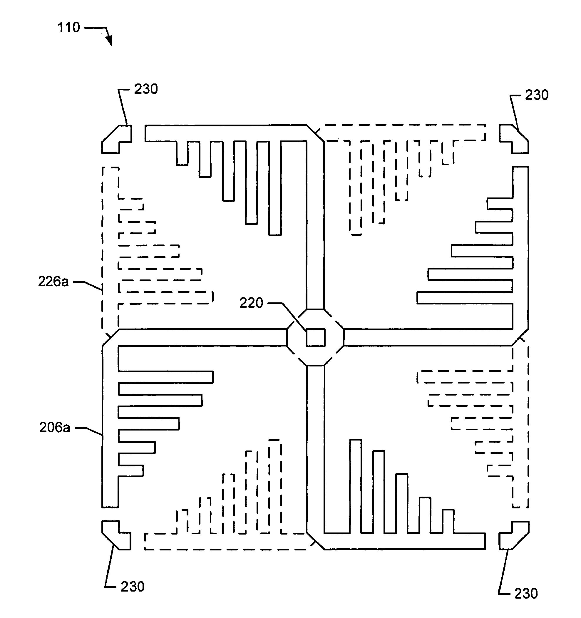
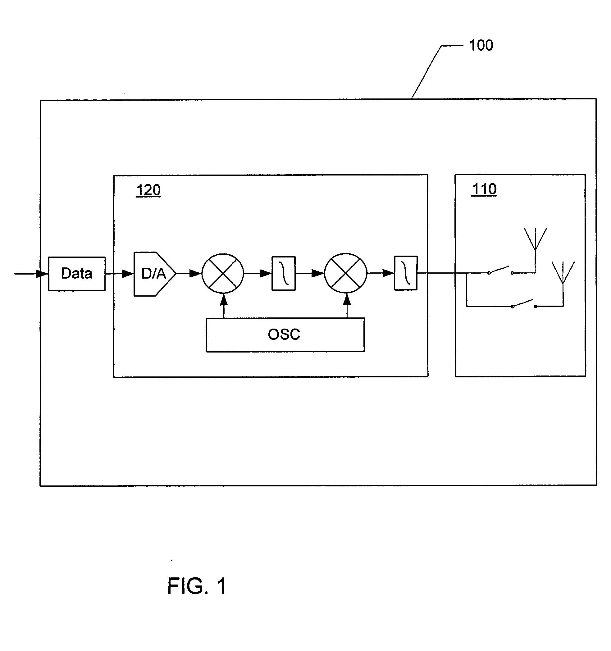
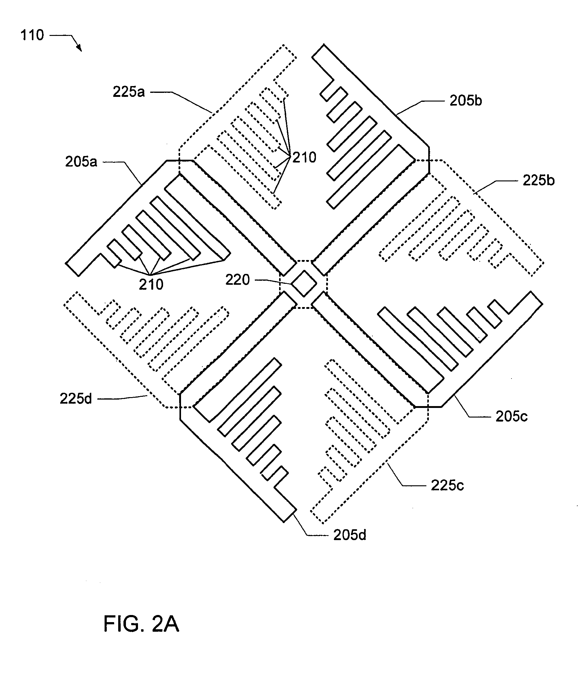
[0022]A system for a wireless (i.e., radio frequency or RF) link to a remote receiving device includes a communication device for generating an RF signal and an antenna apparatus for transmitting and / or receiving the RF signal. The antenna apparatus comprises a plurality of substantially coplanar modified dipoles. Each modified dipole provides gain (with respect to isotropic) and a horizontally polarized directional radiation pattern. Further, each modified dipole has one or more loading structures configured to decrease the footprint (i.e., the physical dimension) of the modified dipole and minimize the size of the antenna apparatus. With all or a portion of the plurality of modified dipoles active, the antenna apparatus forms an omnidirectional horizontally polarized radiation pattern.

[0023]Advantageously, the loading structures decrease the size of the antenna apparatus, and allow the system to be made smaller. The antenna apparatus is easily manufactured from common planar subst...


PUM


Abstract

A system and method for a wireless link to a remote receiver includes a communication device for generating RF and an antenna apparatus for transmitting the RF. The antenna apparatus comprises a plurality of substantially coplanar modified dipoles. Each modified dipole provides gain with respect to isotropic and a horizontally polarized directional radiation pattern. Further, each modified dipole has one or more loading structures configured to decrease the footprint (i.e., the physical dimension) of the modified dipole and minimize the size of the antenna apparatus. The modified dipoles may be electrically switched to result in various radiation patterns. With multiple of the plurality of modified dipoles active, the antenna apparatus may form an omnidirectional horizontally polarized radiation pattern. One or more directors may be included to concentrate the radiation pattern. The antenna apparatus may be conformally mounted to a housing containing the communication device and the antenna apparatus.

Description

CROSS-REFERENCE TO RELATED APPLICATIONS[0001]This application claims the benefit of U.S. Provisional Application No. 60 / 602,711 titled “Planar Antenna Apparatus for Isotropic Coverage and QoS Optimization in Wireless Networks,” filed Aug. 18, 2004; and U.S. Provisional Application No. 60 / 603,157 titled “Software for Controlling a Planar Antenna Apparatus for Isotropic Coverage and QoS Optimization in Wireless Networks,” filed Aug. 18, 2004, which are hereby incorporated by reference.BACKGROUND OF INVENTION[0002]1. Field of the Invention[0003]The present invention relates generally to wireless communications, and more particularly to a system and method for a horizontally polarized antenna apparatus with selectable elements.[0004]2. Description of the Prior Art[0005]In communications systems, there is an ever-increasing demand for higher data throughput, and a corresponding drive to reduce interference that can disrupt data communications. For example, in an IEEE 802.11 network, an a...

Claims


Application Information

Patent Timeline
Patent Type & Authority Patents(United States)
IPC IPC(8): H01Q9/28H01Q1/48
CPCH01Q3/24H01Q9/285H01Q21/205H01Q21/26
Inventor SHTROM, VICTORKISH, WILLIAM S.
Owner ARRIS ENTERPRISES LLC
Why Eureka
Try Eureka