Eccentric swivel mechanism for a vehicle seat

a vehicle seat and swivel mechanism technology, applied in the field of vehicle seats, can solve the problems of affecting the seat size, affecting the operation of the vehicle control, and the operator having to assume an awkward position to operate the vehicle control,

Active Publication Date: 2008-04-29
BRUNSWICK CORPORATION
View PDF47 Cites 43 Cited by
  • Summary
  • Abstract
  • Description
  • Claims
  • Application Information

AI Technical Summary

Problems solved by technology

Oftentimes, however, a vehicle seat rotating about a fixed central axis requires excessive clearance between the vehicle seat and a vehicle wall in order to permit free rotating movement, necessitating the mounting of the swivel mechanism further away from any sidewall obstacle than if the seat did not rotate.
The movement of the seat mount away from the sidewall may result in the misalignment between the central axis of the vehicle controls, such as for example a wheel, and the central axis of the vehicle seat, causing an operator to have to assume an awkward position to operate the vehicle controls.
Thus, in a vehicle with limited dimensions, such as for example a marine vehicle, the size and placement of the vehicle seat may result in wasted space, the alteration of seat dimensions due to the rotational constraints, and / or the misalignment between the vehicle controls and the seat mechanism.
Unfortunately, in the case of boats, for example, a wide range of seat designs and seating layouts typically requires boat manufacturers to design base support locations to a wide range of vehicle seats, and allow for dimensional variants based upon the numerous vehicle seat designs.
Further, the wide range of seat designs and layouts sometimes result in a more centrally located base support to allow adequate rotational clearance, which can result in significantly less operating space for vehicle occupants.
Such mechanisms, however, are typically designed for rotation of large, bulky, elongated seats, and therefore are not particularly well suited for adaptation to smaller vehicle seats.

Method used


Image

  • Eccentric swivel mechanism for a vehicle seat
  • Eccentric swivel mechanism for a vehicle seat
  • Eccentric swivel mechanism for a vehicle seat

Examples


Embodiment Construction

[0019]The following description is not intended to limit the scope of the invention to the precise form or forms detailed herein. Instead the following description is intended to be illustrative of the principles of the invention so that others may follow its teachings.

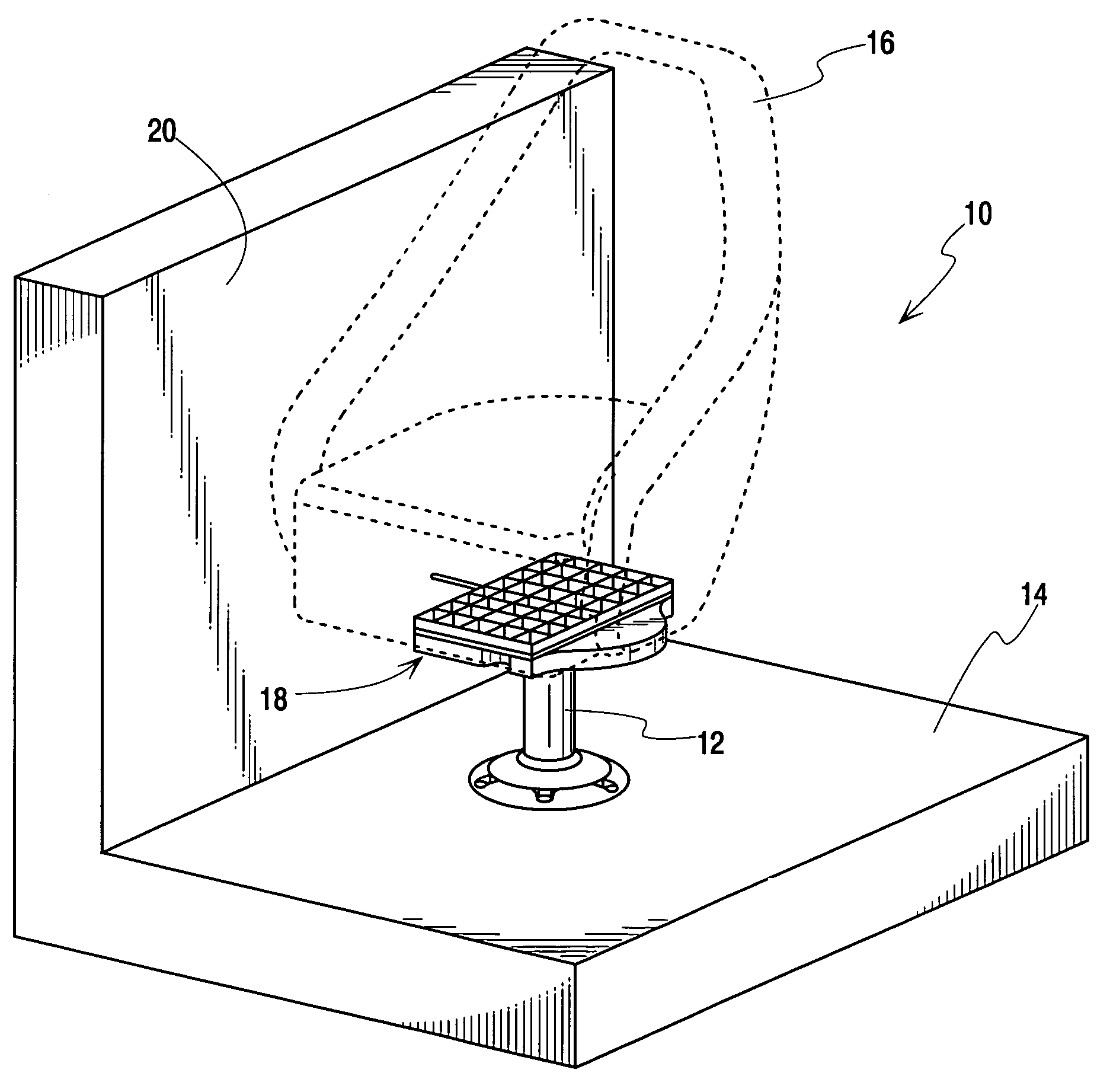
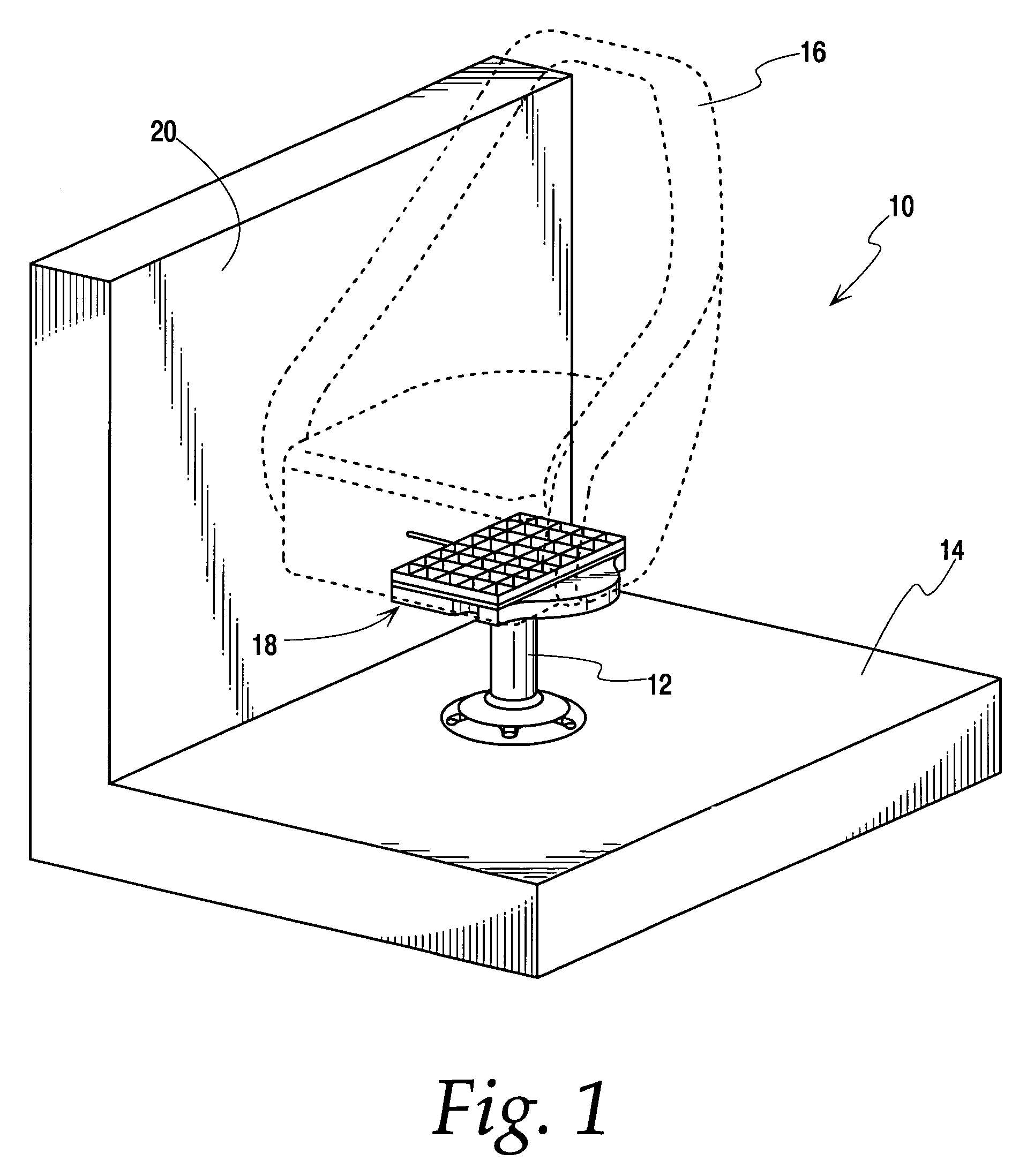
[0020]Referring now to FIG. 1, an example vehicle seat assembly 10 is shown. The seat assembly 10 includes a base pedestal 12 mounted to a vehicle floor 14 and adapted to support a seat 16 (shown in phantom lines in FIG. 1) via an eccentric swivel seat mount 18. The eccentric swivel seat mount 18 allows the seat 16 to be rotated from a front facing position to a rear facing position, as described in detail below. In this example, the seat 16 may be any suitable marine seat such as, for instance, an AVENIR™ marine seat marketed by the Attwood Corporation, Lowell, Mich.

[0021]As will be appreciated by one of ordinary skill in the art, the seat 16 typically is constructed with varying length, width, height, and turning di...


PUM


Abstract

A swivel mechanism for a vehicle seat includes a base plate configured to be fixed relative to the vehicle and to provide support to the vehicle seat. The vehicle seat is mounted to a seat mounting plate having a first side configured to receive the vehicle seat and a second side opposite the first side, mechanically coupled to the base plate. The seat mounting plate and the base plate are mechanically coupled so that when the seat mounting plate is rotated about an axis of the base plate the seat mounting plate translates in a plane that is substantially perpendicular to the axis of the base plate. A locking recess is formed in one of the base plate or the seat mounting plate, and is adapted to receive a locking pawl pivotably mounted to the opposite one of the base plate or the seat mounting plate. The locking recess is biased toward the locking recess such that when the locking pawl and locking recess are engaged, the seat mounting plate is inhibited from movement relative to the base plate.

Description

FIELD OF THE DISCLOSURE[0001]The present disclosure relates generally to vehicle seats and, more specifically, to an eccentric swivel mechanism for vehicle seats.BACKGROUND OF RELATED ART[0002]Many vehicle seats such as those used in automobiles, boats, trains, industrial or commercial vehicles, etc. include a swivel seat mechanism that enables a seated vehicle occupant to rotate their seat clockwise or counterclockwise to a desired position about a pedestal. Use of the swivel mechanism typically allows the seat occupant to adjust the direction of their seat for ease of use of vehicle controls, comfort, safety, recreational use, etc.[0003]Typically, vehicle seat swivel mechanisms only allow the user to rotate the vehicle seat about a central axis. Oftentimes, however, a vehicle seat rotating about a fixed central axis requires excessive clearance between the vehicle seat and a vehicle wall in order to permit free rotating movement, necessitating the mounting of the swivel mechanism ...

Claims


Application Information

Patent Timeline
Patent Type & Authority Patents(United States)
IPC IPC(8): A47C3/18
CPCA47C3/18B60N2/14B60N2/146B63B29/06
Inventor BEGIN, JASON ERNESTNYENHUIS, JACK ROBERTRUSTER, MATTHEW RYEN
Owner BRUNSWICK CORPORATION
Why Eureka
Try Eureka