Tube connector

a technology of tube connectors and connectors, applied in the direction of hose connections, couplings, mechanical devices, etc., can solve the problems of providing stagnant regions and potential hazards, and achieve the effect of improving the tube connector

Active Publication Date: 2008-05-13
BIO PURE TECH LTD
View PDF10 Cites 41 Cited by
  • Summary
  • Abstract
  • Description
  • Claims
  • Application Information

AI Technical Summary

Problems solved by technology

However the connection between the hollow spigot and the tubing can provide a stagnant region and a potential hazard.
The pressure of the fluid is liable to force the fluid right up the taper and cause a leak or at least leave a residue of the fluid between the tube and the taper.

Method used


Image

  • Tube connector
  • Tube connector
  • Tube connector

Examples


Embodiment Construction

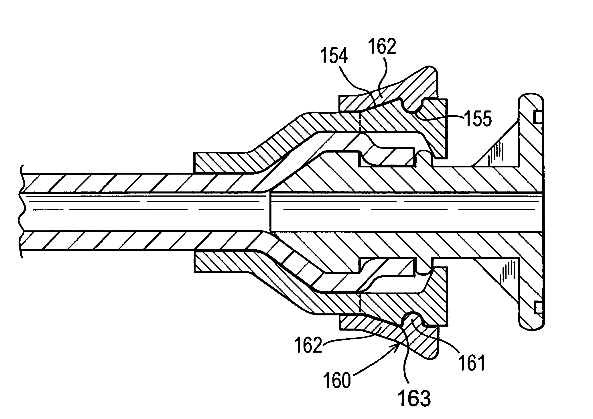
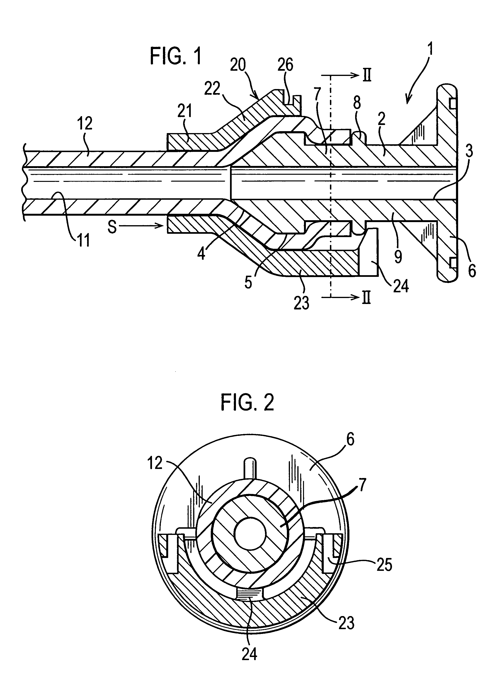
[0025]Referring to FIGS. 1 to 4 of the drawings, the tube connector 1 has a flanged spigot 2 with a uniform bore 3 of the same size as the internal bore 11 of an elastomeric tube 12 that is to be connected by the connector.

[0026]The spigot has a frusto-conical end 4, backed up by a short length 5 having a uniform diameter the same as the maximum conical diameter. Next towards the flange 6 is a plain length 7 of lesser diameter. Then there is an annular rib 8 of diameter greater than that of the short length and finally a further length 9 to the flange.

[0027]For holding the tube on the spigot an outer collar 20 is provided. It has a plain outer end 21 with an internal diameter the same as that of the outer diameter of the tube. Next to the plain end it has an outwards tapering length 22. This follows the taper of the spigot, i.e. has the same angle, and has the same length. The flange end 23 of the collar has a constant internal diameter. From a position corresponding to midway along...


PUM

PropertyMeasurementUnit
diameteraaaaaaaaaa
resistanceaaaaaaaaaa
pressureaaaaaaaaaa

Abstract

A connector for a tube comprises a hollow spigot and an outer securing member for capturing a tube therebetween. The hollow spigot includes an internal bore matched to that of the tube, a tapered end with a frusto-conical length and its small diameter at its distal end and a parallel length inwards of the tapered end, with a diameter less than the maximum tapered diameter and an annular rib inwards of the parallel length to provide an end stop for the tube when fitted onto the spigot. The outer securing member includes an internal tapered bore matched to the frusto-conical length and of respectively increased diameter to accommodate the tube therebetween and at least one latch formation spaced from the member's large tapered end for engaging behind the annular rib.

Description

CROSS-REFERENCE TO RELATED APPLICATION[0001]The present application claims priority under 35 USC §119 to United Kingdom Patent Application No. 0402564.9 filed on Feb. 5, 2004.TECHNICAL FIELD[0002]The present invention relates to a tube connector, particularly though not exclusively, for use in contamination sensitive applications.BACKGROUND OF THE INVENTION[0003]Fluid connections in food and pharmaceutical industries are commonly made with flanged connectors clamped to each other. The connectors have hollow spigots to which tubing is connected in a fluid-tight manner. The flanged connectors can be made to tight tolerances, as can seals between two flanges, whereby there is little scope for stagnant accumulation at the flanges per se of material which can become contaminated, for instance by bacteria, and hence cause a hazard.[0004]However the connection between the hollow spigot and the tubing can provide a stagnant region and a potential hazard. This arises because the nose of the ...

Claims


Application Information

Patent Timeline
Patent Type & Authority Patents(United States)
IPC IPC(8): F16L33/00F16L33/22
CPCF16L33/225Y10S285/921
Inventor MAUNDER, ROY PETERHILTON, DAVID WHITMORE
Owner BIO PURE TECH LTD
Why Eureka
Try Eureka