Displacement lock MLT

a technology of locking ties and locking clips, which is applied in the direction of hose connections, bundling articles, other domestic articles, etc., and can solve problems such as the release of the tightened strap

Inactive Publication Date: 2008-05-20
PANDUIT
View PDF21 Cites 44 Cited by
  • Summary
  • Abstract
  • Description
  • Claims
  • Application Information

AI Technical Summary

Problems solved by technology

None of the prior devices were positive locking, i.e. depending on the orientation of the locking head, gravity could hold the ball out of locking engagement with the strap resulting in release of the tightened strap.

Method used


Image

  • Displacement lock MLT
  • Displacement lock MLT
  • Displacement lock MLT

Examples


first embodiment

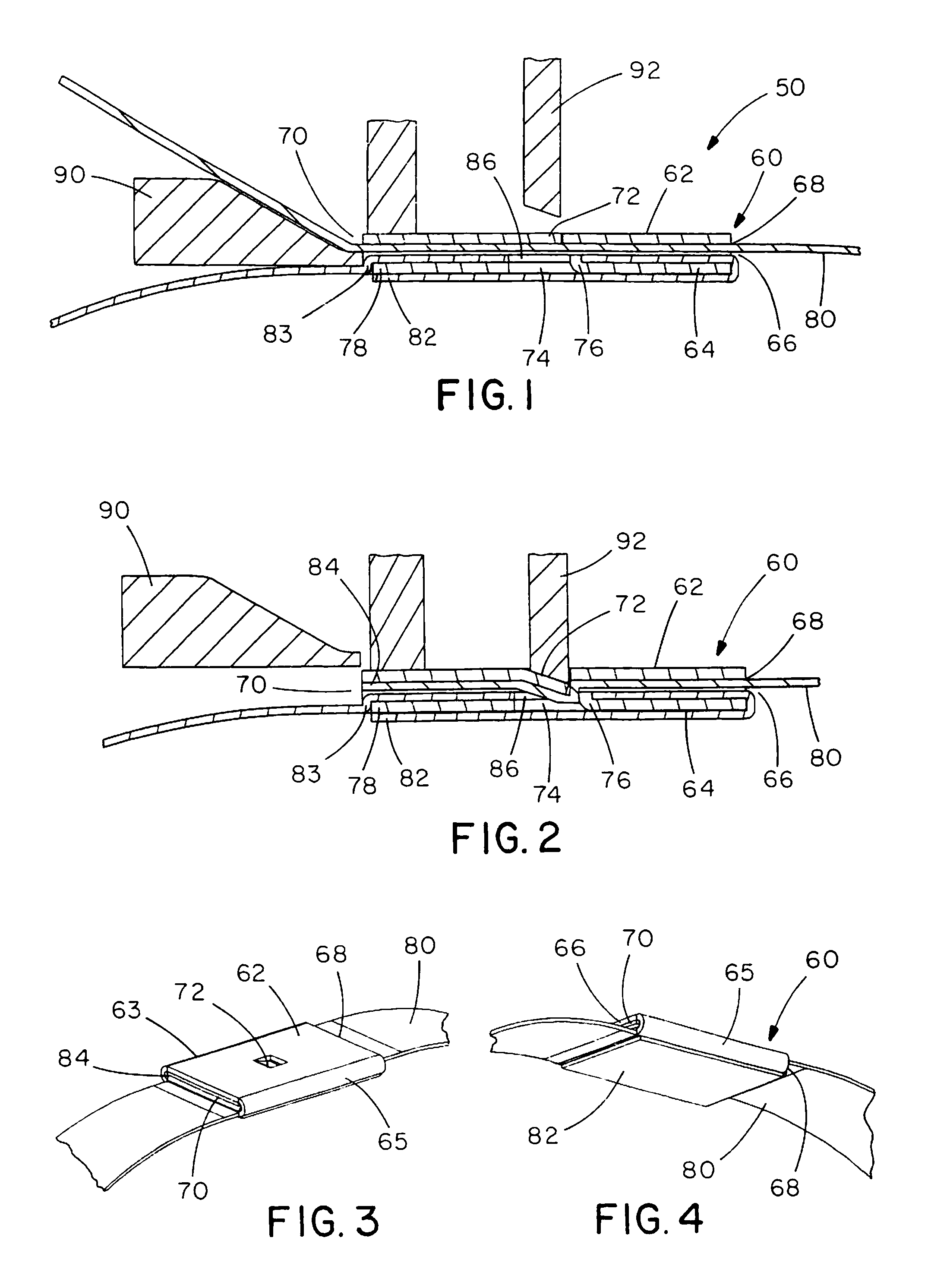
[0046]the metal locking tie of the present invention is illustrated in FIGS. 1-4. The metal locking tie 50 includes a metallic locking head 60 and an elongate metallic strap 80 with a first end 82 and a second end 84. The head 60 includes a top wall 62, a bottom wall 64, sides 63, 65 and a strap passageway 66 with an entrance end 68 and an exit end 70. The top wall 62 of the head 60 includes a top tab 72 positioned at the center of the head. As will be discussed below, the top tab 72 bends downward towards the strap passageway 66 in the head 60 when a locking punch 92 engages the top tab 72. The bottom wall 64 of the head 60 includes an aperture 74 positioned at the center of the head 60. The bottom wall 64 also includes a bottom tab 76 positioned adjacent to the aperture 74. The bottom tab 76 extends upwards towards the strap passageway 66.

[0047]As illustrated in FIGS. 1 and 2, the first end 82 of the strap 80 is positioned along the bottom wall 64 of the head 60. The strap 80 wrap...

second embodiment

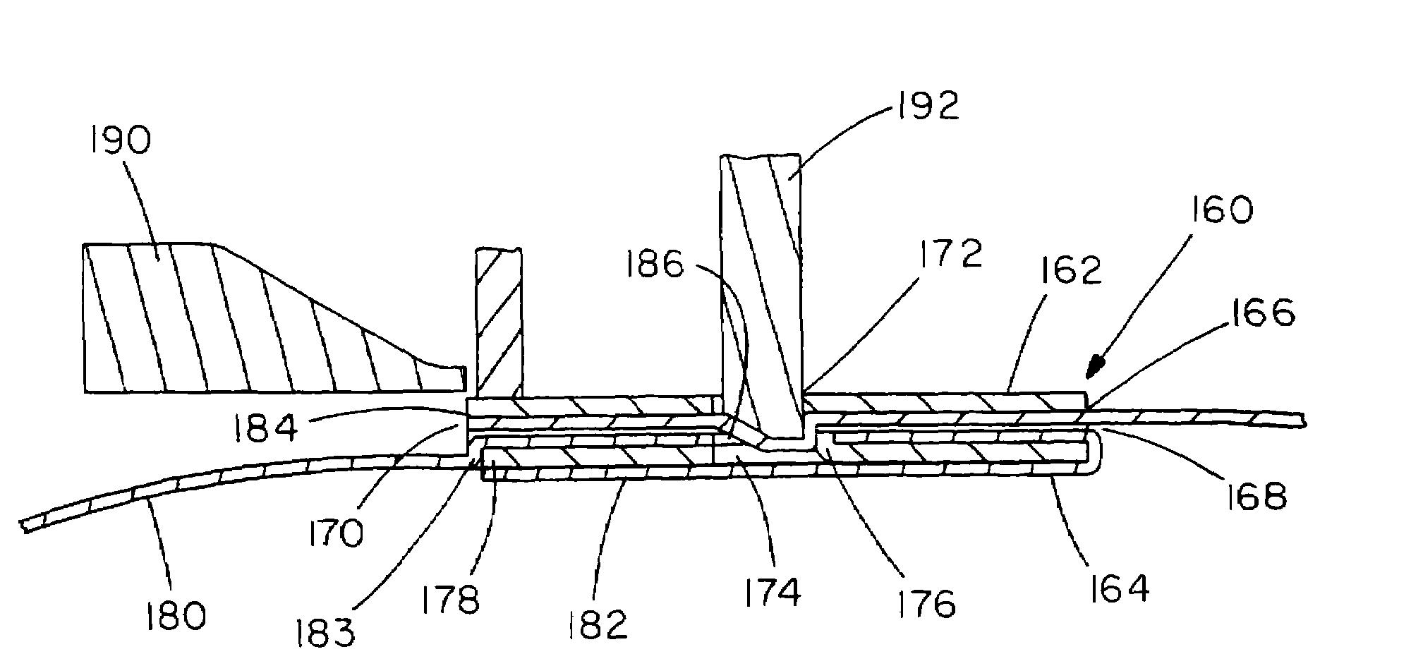
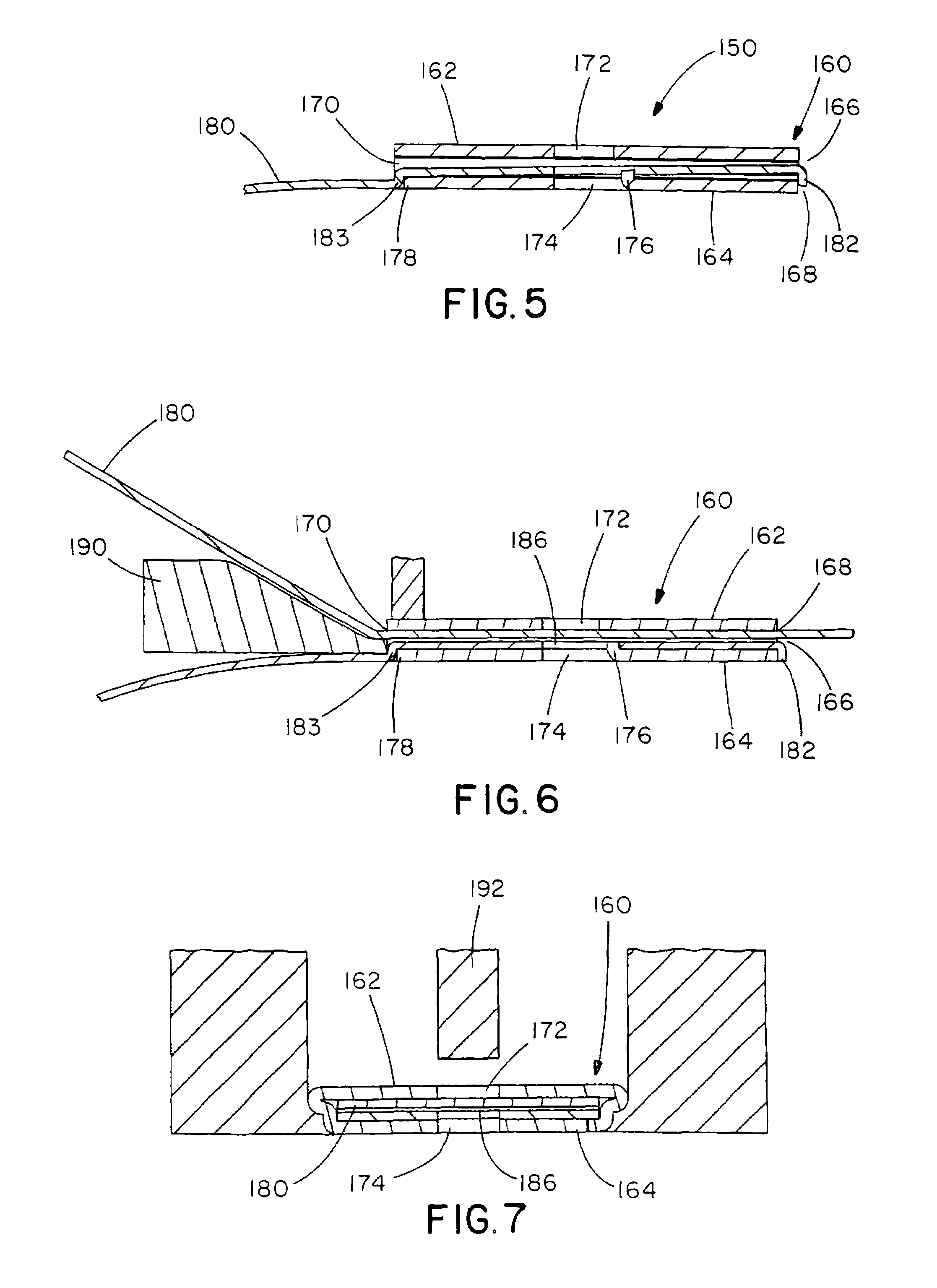
[0052]As shown in FIGS. 5-11, the first end 182 of the strap 180 engages the bottom wall 164 of the locking head 160. The first end 182 of the strap 180 is bent up to create a friction resistance with the second end 184 of the strap 180 when the second end 184 enters the strap passageway 166 in the head. In another variation of the second embodiment, as illustrated in FIGS. 12-15, the first end 182 of the strap 180 may be positioned along the bottom wall 164 of the head 160 such that the strap 180 wraps around the entrance end 168 of the strap passageway 166 and extends through the strap passageway 166.

[0053]Once the strap 180 has been wrapped around the objects to be held or bundled, the second end 184 of the strap 180 is inserted in the entrance end 168 of the strap passageway 166 and through the strap passageway 166. The metal locking tie tool tensions the strap 180 and the tool is activated (see FIGS. 8-9 and 12-13) to secure the strap 180 to the head 160 and to cut the strap 18...


PUM


Abstract

A metal locking tie formed from a locking head and an elongate strap extending through the locking head. The locking head is defined by a top wall, a bottom wall and two sides. The locking head includes a strap passageway that extends through the locking head from an entrance end to an exit end. The bottom wall of the locking head has a tab that extends upwardly toward the strap passageway in the locking head. The strap has a first end, a second end, and an aperture therethrough. When the strap is positioned within the locking head the upwardly extending tab of the locking head engages the aperture in the strap. A metal locking tie tool secures the strap to the locking head by displacing a portion of the strap in the locking head.

Description

CROSS REFERENCE TO RELATED APPLICATION[0001]This application claims priority to U.S. Provisional Application No. 60 / 684,913 filed May 26, 2005, the entire contents of which are hereby incorporated by reference.FIELD OF THE INVENTION[0002]The present invention relates to metal locking ties, and more particularly to metal locking ties with a locking mechanism that displaces the strap within the locking head to lock the strap in the locking head.BACKGROUND OF THE INVENTION[0003]Metallic bundling devices incorporating locking balls and roller pins have been used for bundling bales of cotton or the like since the Nineteenth Century. None of the prior devices were positive locking, i.e. depending on the orientation of the locking head, gravity could hold the ball out of locking engagement with the strap resulting in release of the tightened strap. U.S. Pat. No. 4,399,592 addressed this problem by teaching the addition of a raised portion or protuberance for deflecting the threaded strap a...

Claims


Application Information

Patent Timeline
Patent Type & Authority Patents(United States)
IPC IPC(8): F16L33/00
CPCB65B13/027B65D63/08Y10T24/1457Y10T24/1459Y10T24/1467B65D63/02
Inventor CAVENEY, JACK E.BULANDA, JOHN J.HARTMAN, SCOTT R.
Owner PANDUIT
Why Eureka
Try Eureka