Structure and process for composite free layer in CPP GMR device

a technology of cpp gmr and composite free layer, which is applied in the direction of nanoinformatics, instruments, transportation and packaging, etc., to achieve the effect of improving the mr ratio

Inactive Publication Date: 2008-06-24
HEADWAY TECH INC
View PDF9 Cites 15 Cited by
  • Summary
  • Abstract
  • Description
  • Claims
  • Application Information

AI Technical Summary

Benefits of technology

[0013]It has been an object of at least one embodiment of the present invention to provide a CPP GMR magnetic read head having an improved MR ratio as well as a free layer that is magnetically soft.

Problems solved by technology

However there is some concern regarding the free layer magnetic softness because CoFe / FeNi deposited on top of alumina or copper will not be as soft as CoFe / NiFe.

Method used


Image

  • Structure and process for composite free layer in CPP GMR device
  • Structure and process for composite free layer in CPP GMR device

Examples


Embodiment Construction

[0019]In a CPP spin valve structure having a free layer such as Fe50Co, higher spin polarization ferromagnetic material can improve CPP GMR significantly. It is also known that Fe rich NiFe has higher spin polarization. The present invention shows how this may be applied to the NiFe component of the free layer to improve the CPP GMR.

[0020]Instead of using single composition NiFe layer both Fe rich (FeNiy) and Ni rich (NizFe) layers are combined as part of the free layer of a TMR or CPP sensor. By adjusting FeNi and NiFe thickness and composition it becomes possible to improve the magnetic softness of the free layer and still maintain the higher MR ratio.

[0021]Because of the magnetostriction consideration, FeNi-(30-34 at %) and 80-83 at %-NiFe were selected as the most suitable candidates.

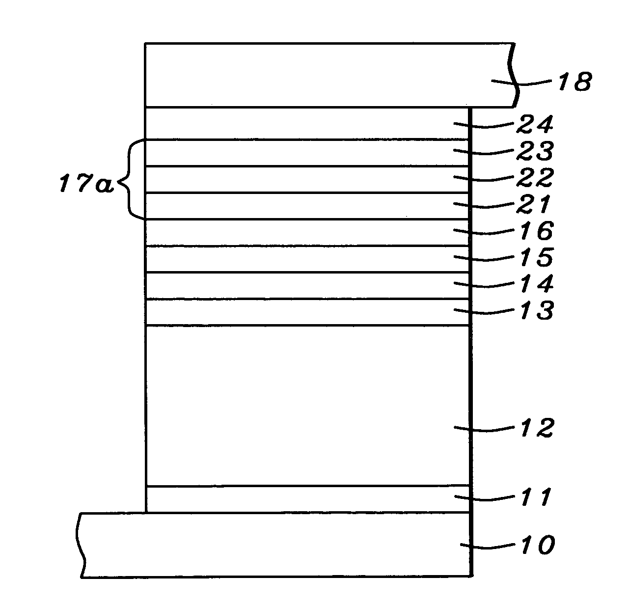
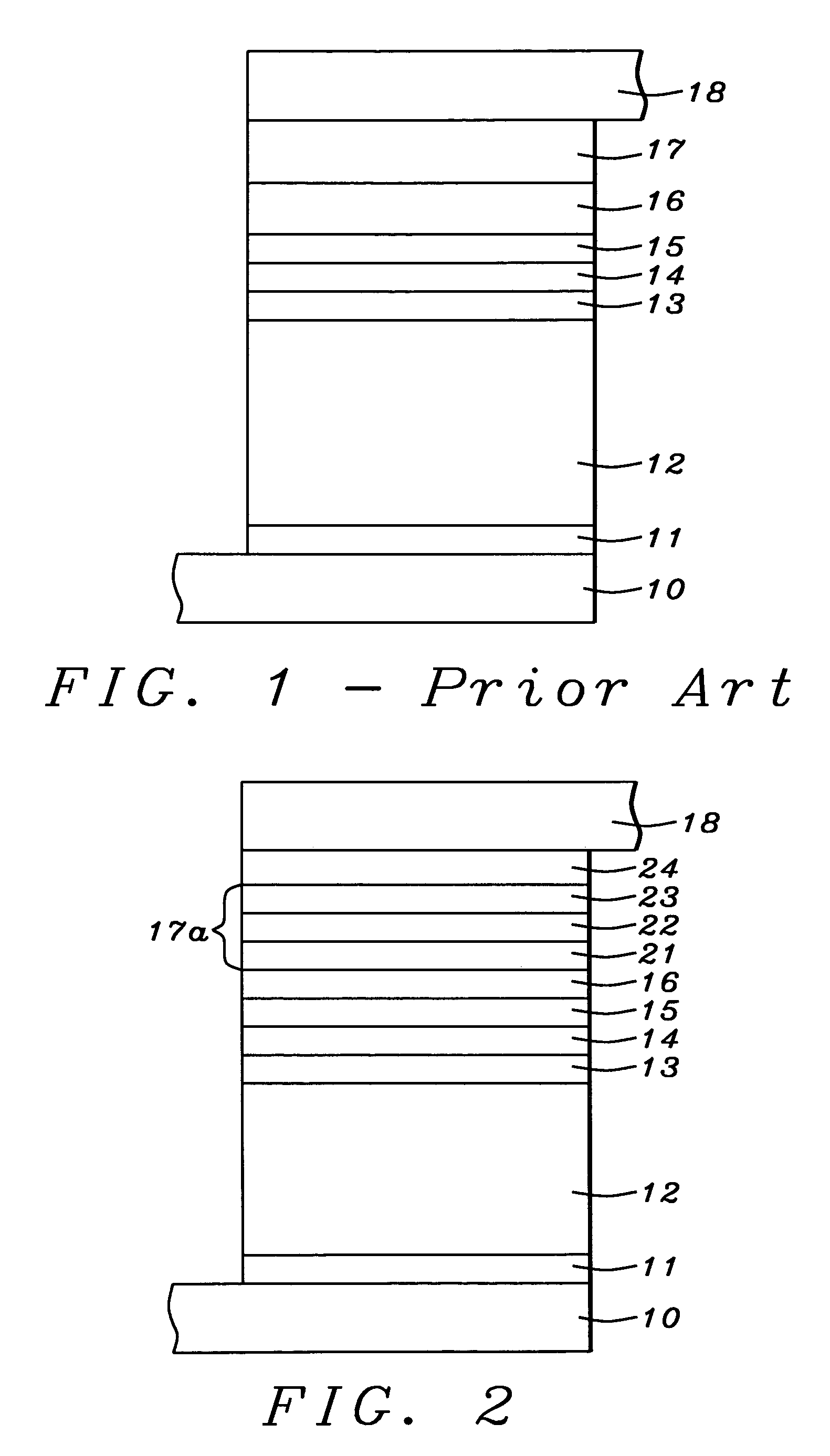
[0022]Referring now to FIG. 2, we provide a description of the process of the present invention. In the course of this description, the structure of the present invention will also become apparent.

[...


PUM

PropertyMeasurementUnit
thicknessaaaaaaaaaa
thicknessaaaaaaaaaa
thicknessaaaaaaaaaa

Abstract

The conventional free layer in a CPP GMR read head has been replaced by a tri-layer laminate comprising Co rich CoFe, moderately Fe rich NiFe, and heavily Fe rich NiFe. The result is an improved device that has a higher MR ratio than prior art devices, while still maintaining free layer softness and acceptable magnetostriction. A process for manufacturing the device is also described.

Description

FIELD OF THE INVENTION[0001]The invention relates to the general field of CPP GMR read heads with particular reference to the free layer sub-structure.BACKGROUND OF THE INVENTION[0002]The principle governing the operation of most magnetic read heads is the change of resistivity of certain materials in the presence of a magnetic field (magneto-resistance or MR). Magneto-resistance can be significantly increased by means of a structure known as a spin valve where the resistance increase (known as Giant Magneto-Resistance or GMR) derives from the fact that electrons in a magnetized solid are subject to significantly less scattering by the lattice when their own magnetization vectors (due to spin) are parallel (as opposed to anti-parallel) to the direction of magnetization of their environment.[0003]The key elements of a spin valve are illustrated in FIG. 1. They are seed layer 11 (lying on lower conductive lead 10) on which is antiferromagnetic layer 12 whose purpose is to act as a pin...

Claims


Application Information

Patent Timeline
Patent Type & Authority Patents(United States)
IPC IPC(8): B05D5/12
CPCB82Y10/00B82Y25/00G11B5/3909G11B5/3929Y10T428/1121Y10T428/11Y10T428/1107Y10T428/1129Y10T29/49044G11B2005/3996
Inventor WANG, HUI-CHUANLI, MINZHAO, TONGZHANG, KUNLIANGTORNG, CHYU-JIUH
Owner HEADWAY TECH INC
Why Eureka
Try Eureka