TMR element having a tunnel barrier which includes crystalline portions and non-crystalline portions

a tunnel barrier and element technology, applied in the field of magnetoresistive elements, can solve the problems of large internal stress, direct external stress on the tunnel barrier layer, etc., and achieve the effect of improving the mr ratio

Active Publication Date: 2010-02-09
TDK CORPARATION
View PDF2 Cites 0 Cited by
  • Summary
  • Abstract
  • Description
  • Claims
  • Application Information

AI Technical Summary

Benefits of technology

[0012]It is an object of the present invention to provide a magneto-resistive element having an improved MR ratio by preventing in-plane stress in the tunnel barrier layer having a crystalline structure.
[0015]The tunnel barrier layer, which is arranged between the upper layer and the lower layer, may suffer from in-plane tensile and compressive stress at the interfaces on the upper layer and on the lower layer. This stress is thought to be caused by the in-plane stress, which is generated during the formation of other layers that constitute the magneto-resistive element or during the formation of layers that are stacked together with the magneto-resistive element, and which is transmitted via the upper layer and the lower layer. If crystalline portion is continuously formed in the tunnel barrier layer, the tunnel barrier layer may be directly subject to these external stresses, and may suffer from large internal stress. However, in the present invention, since the tunnel barrier layer is formed such that crystalline portions and non-crystalline portions co-exist in a plane that is parallel with the surface of the tunnel barrier layer, the non-crystalline portions absorb the stress. Thus, the internal stress is localized and limited though the external stresses are similarly applied. Accordingly, large in-plane stress is prevented in the tunnel barrier layer, and the tunnel barrier becomes more resistive against damage due to the stress. Additionally, since the sense current flows between the lower layer and the upper layer via the crystalline portions, a sufficient tunneling effect can be ensured.
[0017]As described above, according to the magneto-resistive element of the present invention, since the tunnel barrier layer includes crystalline portions and non-crystalline portions that co-exist in a plane that is parallel with the surface of the tunnel barrier layer, the in-plane stress in the tunnel barrier layer having a crystalline structure is limited, and small cracks are prevented, leading to improvement in the MR ratio. Further, the method for manufacturing the magneto-resistive element of the present invention enables the manufacturing of such a magneto-resistive element.

Problems solved by technology

If crystalline portion is continuously formed in the tunnel barrier layer, the tunnel barrier layer may be directly subject to these external stresses, and may suffer from large internal stress.

Method used


Image

  • TMR element having a tunnel barrier which includes crystalline portions and non-crystalline portions
  • TMR element having a tunnel barrier which includes crystalline portions and non-crystalline portions
  • TMR element having a tunnel barrier which includes crystalline portions and non-crystalline portions

Examples


Embodiment Construction

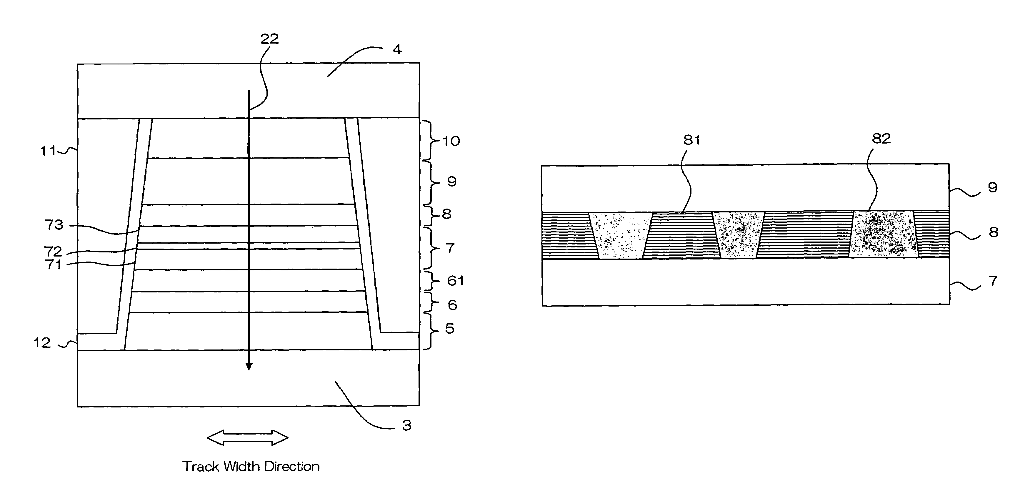
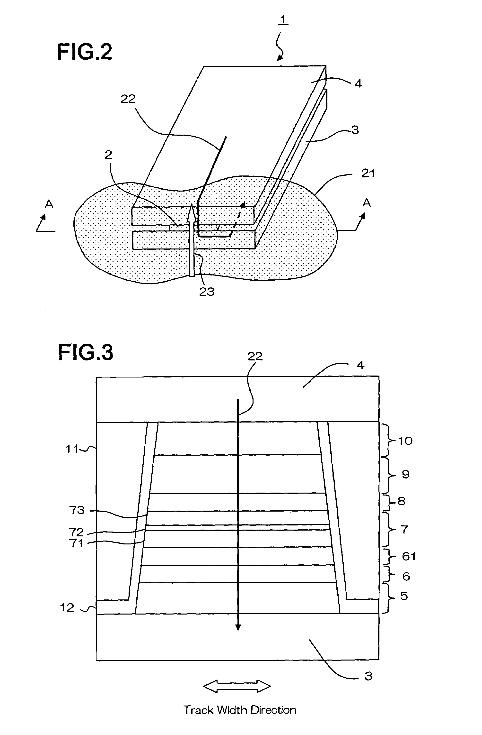
[0035]Explanations are given about embodiments of a magneto-resistive element (hereinafter, called TMR element) according to the present invention with reference to the drawings. As the first embodiment, a TMR element that is applied to a thin film magnetic head used for a hard disk drive is explained. FIG. 2 is a partial perspective view of thin film magnetic head that uses a magneto-resistive element of the present invention. Thin film magnetic head 1 may be a read-only head, or may be a MR / inductive combined head that further includes a write head portion. TMR element 2 is sandwiched between lower electrode 3 and upper electrode 4, and the tip portion thereof is arranged opposite to recording medium 21. Lower electrode 3 and upper electrode 4 have the function of magnetic shield layers for TMR element 2, which is the magneto-resistive element, and the function of electrodes for supplying sense current 22. Sense current 22, which is generated by a voltage that is applied to lower ...


PUM

PropertyMeasurementUnit
thicknessaaaaaaaaaa
temperatureaaaaaaaaaa

Abstract

A magneto-resistive element has a lower layer, a tunnel barrier layer, and an upper layer. The lower layer, the tunnel barrier layer, and the upper layer are disposed adjacent to each other and are stacked in this order. A magnetization direction of either of the lower layer and the upper layer is fixed relative to an external magnetic field, and a magnetization direction of the other layer is variable in accordance with the external magnetic field. A crystalline portion and a non-crystalline portion co-exist in a plane that is parallel with a surface of the tunnel barrier layer.

Description

[0001]The present application is based on, and claims priority from, J.P. Application No. 2005-232302, filed Aug. 10, 2005, the disclosure of which is hereby incorporated by reference herein in its entirety.BACKGROUND OF THE INVENTION[0002]1. Field of the Invention[0003]The present invention relates to a magneto-resistive element and a method for manufacturing the same, particularly to the structure of a TMR element.[0004]2. Description of the Related Art[0005]Conventionally, a GMR (Giant Magneto-Resistive) element using a spin valve (SV) film has widely been used as a magneto-resistive element for a hard disk drive, and, in recent years, a TMR (Tunnel Magneto-Resistive) element is attracting attention as a highly sensitive magneto-resistive element. The TMR element is formed by stacking a lower magnetic layer, a tunnel barrier layer, and an upper magnetic layer in this order. In one embodiment, the lower magnetic layer has a magnetization direction that is fixed relative to the ext...

Claims


Application Information

Patent Timeline
Patent Type & Authority Patents(United States)
IPC IPC(8): G11B5/39G11C11/14
CPCB82Y10/00B82Y25/00B82Y40/00G11B5/3903G11B5/3909G11C11/16H01F10/3254H01F41/307H01L27/222H01L43/08H01L43/12H10B61/00H10N50/01H10N50/10
Inventor UESUGI, TAKUMIMIURA, SATOSHIKAGAMI, TAKEO
Owner TDK CORPARATION
Why Eureka
Try Eureka