
Transmitter

a transmitter and receiver technology, applied in the field of radio transmitters, can solve the problems of short continuous usable time, insufficient practical use, and high efficiency cannot be expected of the conventional class-a and class-ab radio-frequency power amplifiers, and achieve the effect of reducing the delay of the amplitude component in the group

Inactive Publication Date: 2008-07-01
COLLABO INNOVATIONS INC
View PDF6 Cites 32 Cited by
  • Summary
  • Abstract
  • Description
  • Claims
  • Application Information

AI Technical Summary

Benefits of technology

[0023]Accordingly, an object of the present invention is to provide a transmitter capable of realizing a highly efficient EER method where no distortion occurs in the output modulated wave.

Problems solved by technology

However, with the migration to broadband communications, communication methods using subcarriers such as the OFDM have come to be used, and high efficiency cannot be expected of the conventional Class-A and Class-AB radio-frequency power amplifiers.
Consequently, for example, in portable radios using batteries as the power source, the continuous usable time is short, which is inadequate for practical use.
That is, the errors of the amplitude component and the phase component appear as a spectral distortion of the outputted radio-frequency modulated wave and degradation in modulation accuracy.
In addition, for example, when the characteristic of the radio-frequency power amplifier is changed due to fluctuations in temperature or power, since the amount of fluctuations in the error function is increased, a spectral distortion or degradation in modulation accuracy occurs in the radio-frequency modulated wave as a result.
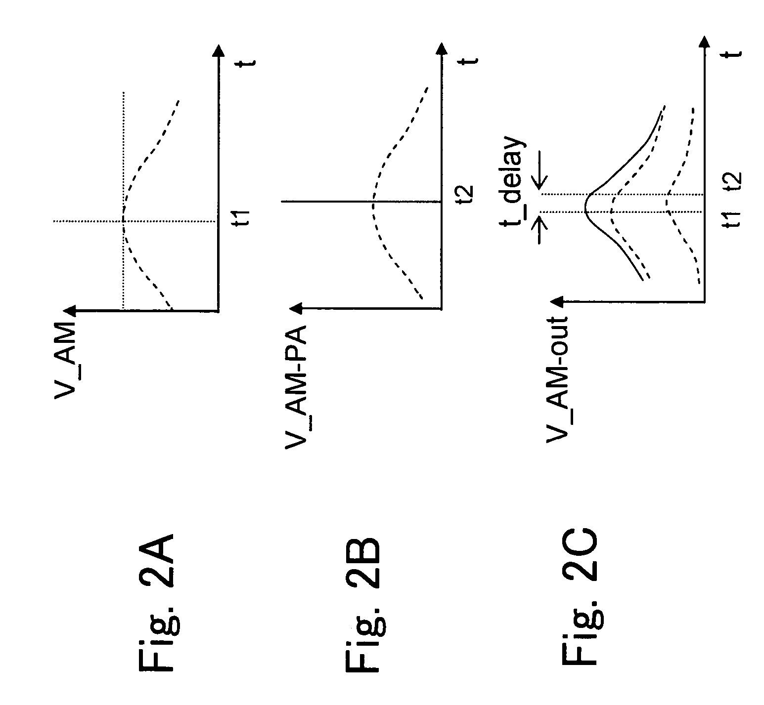
In this case, the following problem arises: When the occurring time delay is the allowable level of the inverse function of the amplitude component and the phase component, the distortion of the radio-frequency modulated wave never occurs.
This appears as a spectral distortion of the modulated wave and degradation in modulation accuracy as a result.

Method used


Image

  • Transmitter
  • Transmitter
  • Transmitter

Examples


first embodiment

[0069]A first embodiment of the present invention will be described with reference to the drawings. The embodiment of the present invention will be described with an IEEE 802.11a wireless LAN system as an example.

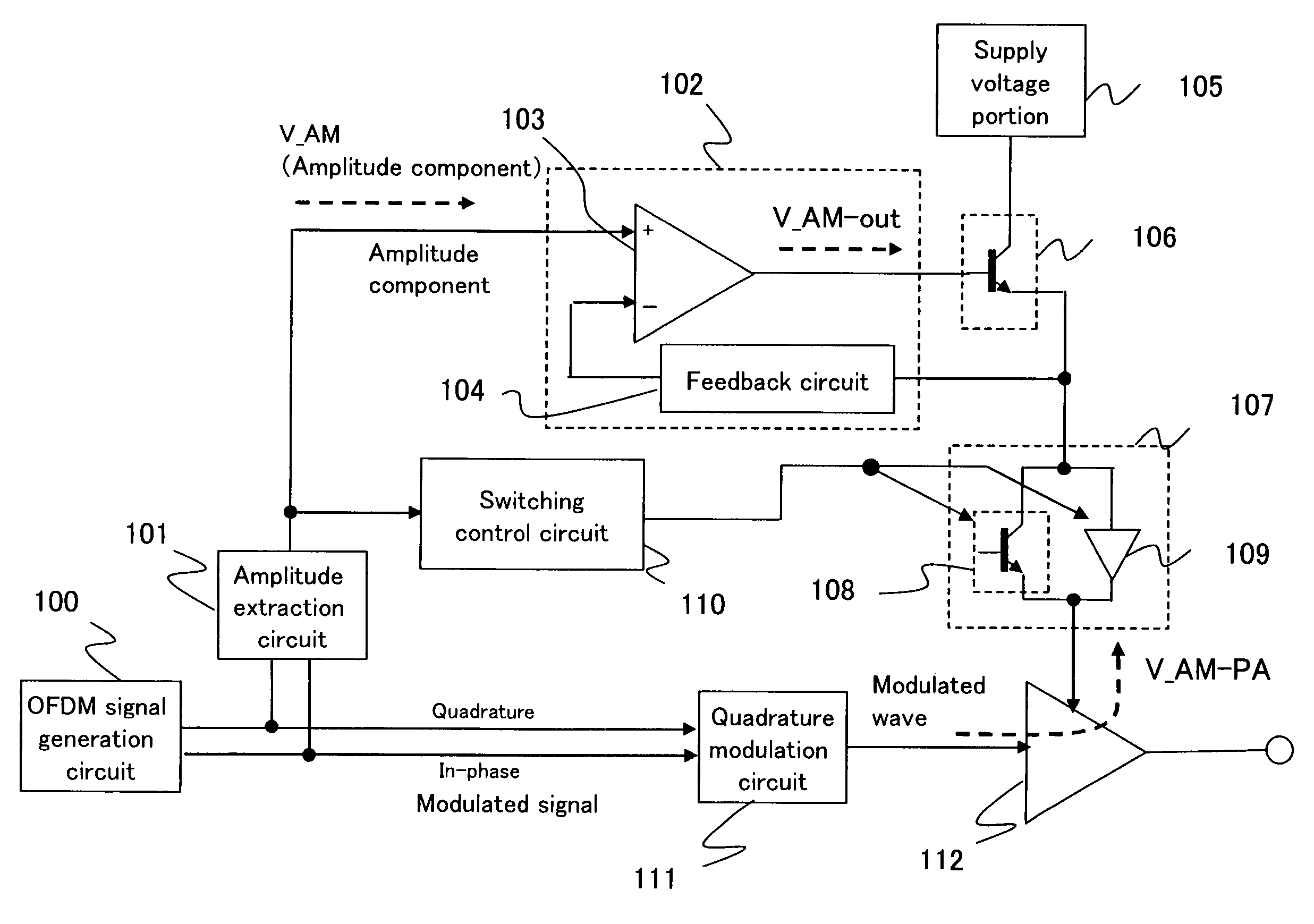
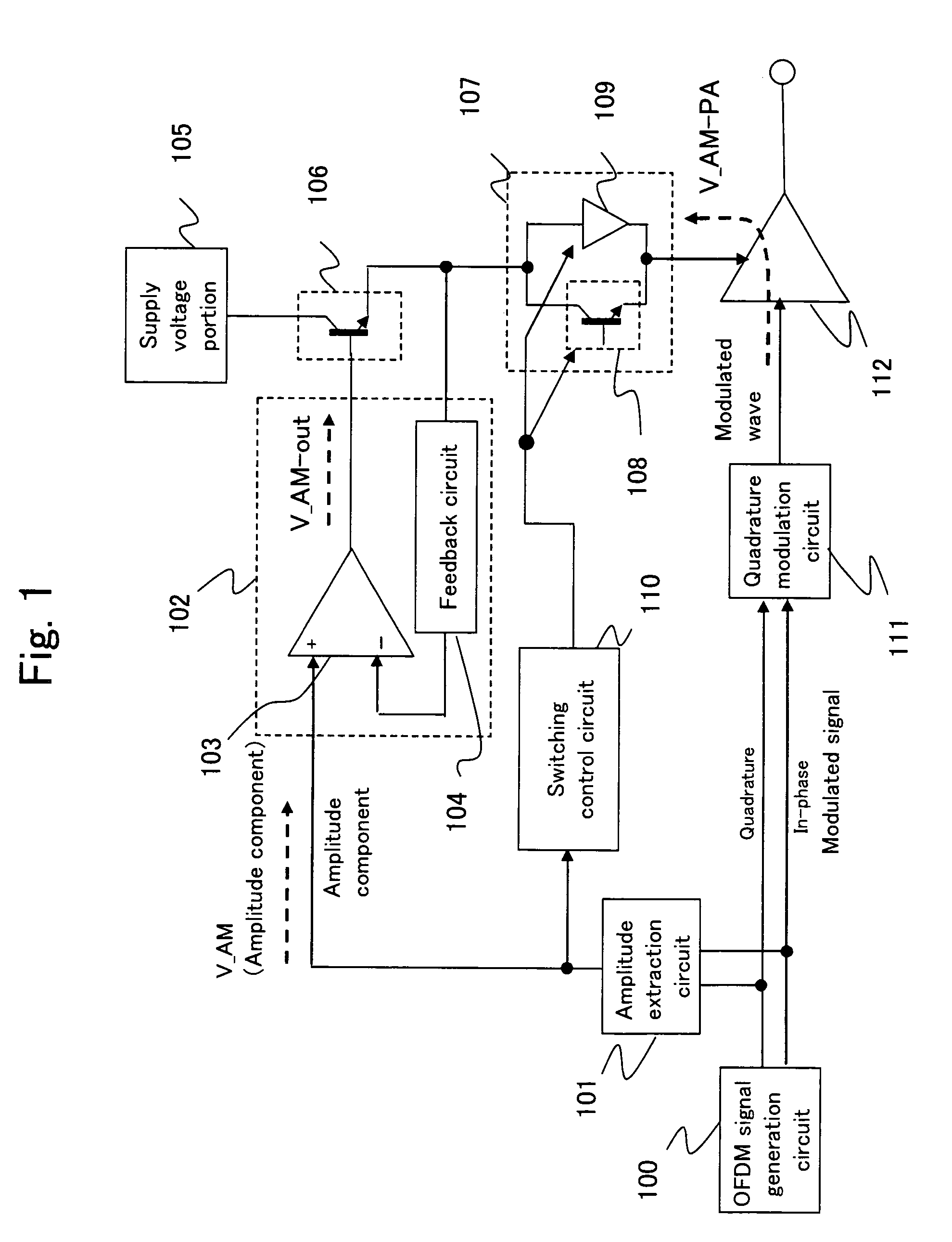
[0070]FIG. 1 is a block diagram of a transmitter according to the first embodiment of the present invention realizing a transmitter using an EER method.

[0071]This transmitter comprises, as shown in FIG. 1, an OFDM signal generation circuit 100, an amplitude extraction circuit 101, an amplitude amplification circuit 102, a supply voltage portion 105, an emitter follower 106, a voltage adjustment circuit 107, a switching control circuit 110, a quadrature modulation circuit 111 and a radio-frequency power amplifier 112.

[0072]The OFDM signal generation circuit 100 generates an OFDM-modulated signal, and corresponds to the modulated signal generating means.

[0073]The amplitude amplification circuit 102 comprises, for example, an operational amplifier 103 and a feedback circuit 10...

second embodiment

[0127]FIG. 7 is a block diagram of a transmitter according to a second embodiment of the present invention. In FIG. 7, the same elements as those of FIG. 1 are denoted by the same reference numerals and descriptions thereof are omitted.

[0128]This transmitter is different from that of the first embodiment in that as shown in FIG. 7, the switching control circuit 110 performs the switching control of the voltage adjustment circuit 107 not according to the amplitude component but according to at least one predetermined power level control signal for specifying the power level of the OFDM modulated signal or at least one data rate control signal for specifying the data rate of the OFDM modulated signal which control signals are outputted from the OFDM signal generation circuit 100.

[0129]The power level control signal and the data rate control signal will be described. In communication systems, in order that the speech quality between communication systems is compensated for so as to be ...


PUM


Abstract

In a transmitter of the present invention, a modulated signal is separated into an amplitude component and a phase component which are inputted to a radio-frequency modulated signal input terminal and a supply voltage terminal of a radio-frequency power amplifier. A voltage adjustment circuit is provided between an output terminal of the radio-frequency power amplifier and an amplitude amplification circuit having a feedback circuit. The voltage adjustment circuit changes the amount of isolation in accordance with the voltage level of the amplitude component. By this, the amplitude component of the radio-frequency modulated wave attenuates the level inputted to the feedback circuit of the amplitude amplification circuit through the supply voltage terminal of the radio-frequency power amplifier.

Description

BACKGROUND OF THE INVENTION[0001]1. Field of the Invention[0002]The present invention relates to a radio transmitter used for communication methods using subcarriers such as the OFDM (orthogonal frequency division multiplex).[0003]2. Prior Art[0004]Generally, for modulated signals involving amplitude modulation, in particular, modulated signals involving multilevel modulation such as QAM (quadrature amplitude modulation), a linear operation is required of the radio-frequency power amplifier for transmitting power to the antenna. For this reason, as the operation class of the radio-frequency power amplifier, Class A and Class AB have been used.[0005]However, with the migration to broadband communications, communication methods using subcarriers such as the OFDM have come to be used, and high efficiency cannot be expected of the conventional Class-A and Class-AB radio-frequency power amplifiers. That is, in the OFDM, high power is instantaneously generated in a completely random fashi...

Claims


Application Information

Patent Timeline
Patent Type & Authority Patents(United States)
IPC IPC(8): H01Q11/12H03C1/62
CPCH03C5/00H04L27/2626H03G3/3042
Inventor AKIZUKI, TAIJITANABE, MITSURU
Owner COLLABO INNOVATIONS INC
Learn More