Latch for tool accessory case

a tool accessory and latch technology, applied in the field of latching mechanism, can solve the problems of easy opening and closing of latches on the case, and difficulty in opening and closing latches

Active Publication Date: 2008-07-22
CREDO TECH CORP +1
View PDF21 Cites 26 Cited by
  • Summary
  • Abstract
  • Description
  • Claims
  • Application Information

AI Technical Summary

Problems solved by technology

While a tool accessory case has the advantage of confining the tool accessory to the inner organizational compartment, the latch on the case may be difficult to open and close, particularly if the user is wearing work gloves or only has one hand available.
Further, some latches are prone to open upon impact, such as when the case is dropped, allowing the tool accessories to escape the tool accessory case.

Method used


Image

  • Latch for tool accessory case
  • Latch for tool accessory case
  • Latch for tool accessory case

Examples


first embodiment

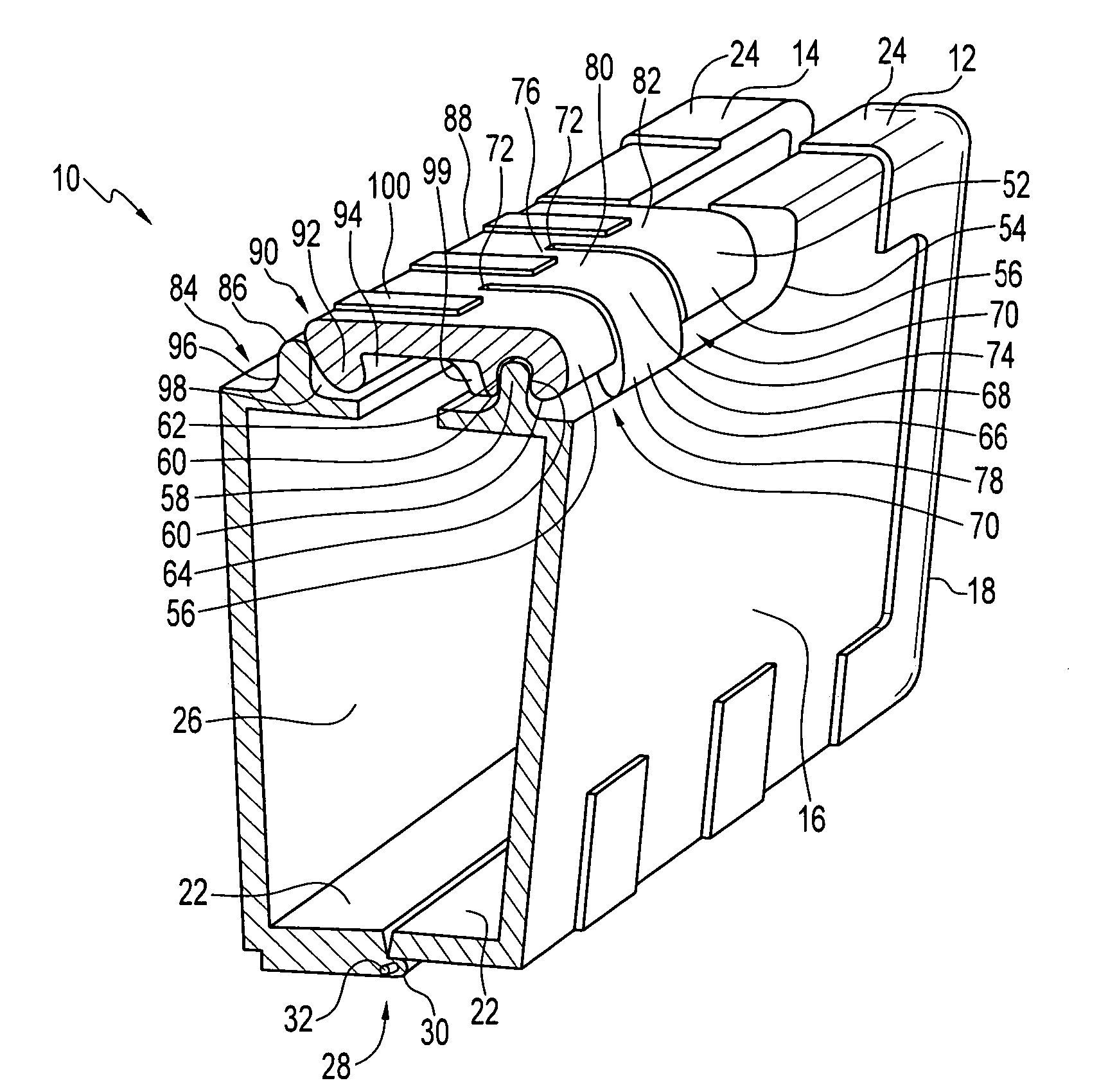
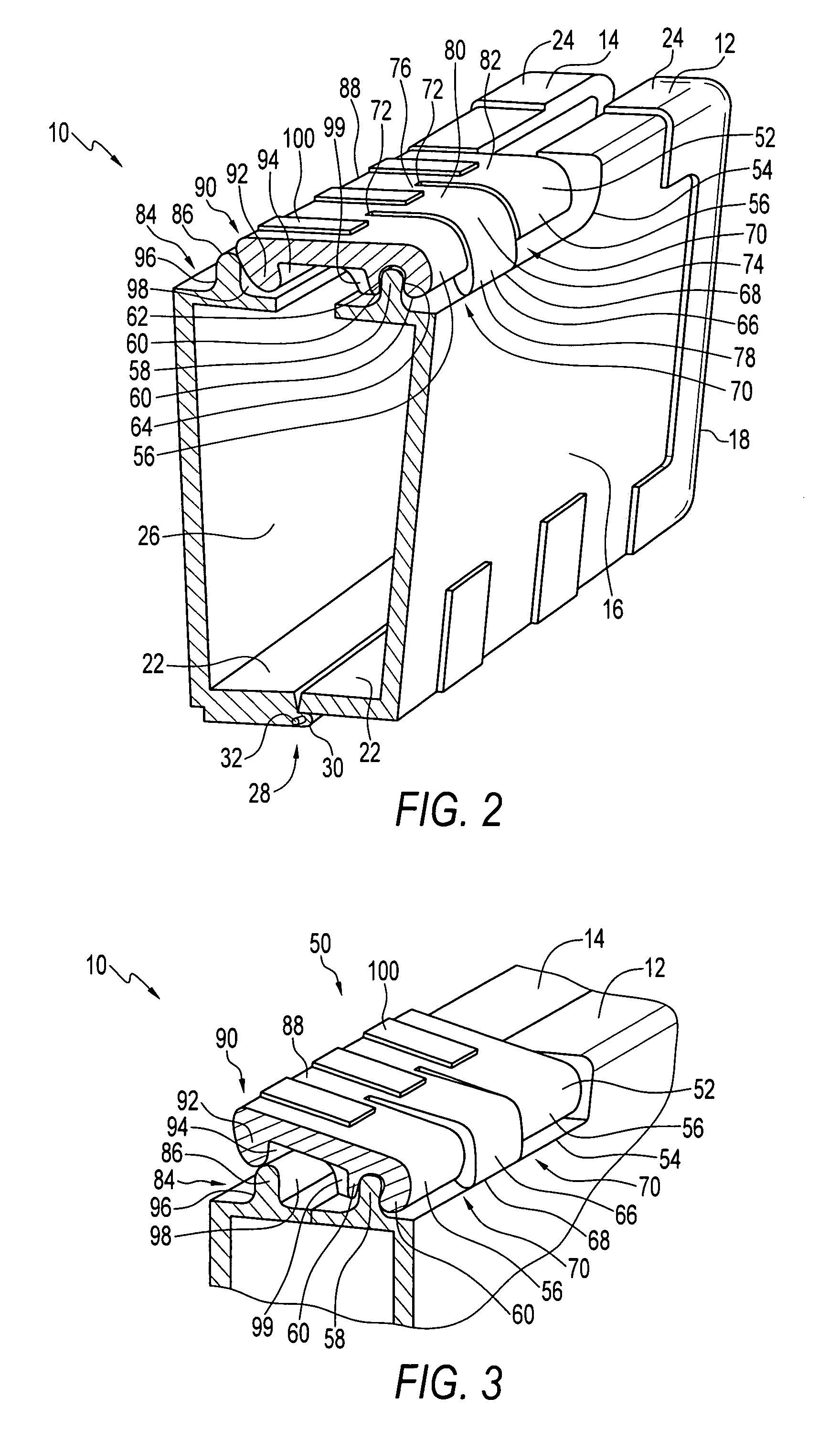
[0029]With reference to FIGS. 2 and 5, the preferably integrally formed latch 150 preferably has three fixed hinge guides 156 on a first portion 152 of the latch. The fixed hinge guides 156 are configured to be pivotally arranged over a raised rib 58 of the first housing member 12. Similar to the latch 50, the fixed hinge guides 156 maintain the latch 150 in pivotal communication with the raised rib 58, and maintains the latch 150 on the first housing member 12.

[0030]Preferably disposed between the fixed hinge guides 156 are the flexure members 166 configured to contact the first housing member 12 at the recess portion 54. The flexure members 166 are preferably integrally formed with the fixed hinge guides 156, and form flexible arms 174 configured to bias the latch 150 generally parallel to the top side 24 of the housing members 12, 14. Vents 170 are preferably disposed between each flexible arm 174 and fixed hinge guide 156.

[0031]Like the latch 50, the flexure members 166 deform t...

third embodiment

[0033]The latch 250 of the third embodiment has a flexure member 266 on a first portion 252 and a gripping structure 290 on a second portion 288. The flexure member 266 is preferably an integrally formed flexible arm 274 which preferably substantially extends the length “L” of the latch 250. The flexible arm 274 preferably extends from the fixed hinge guide 256 and is generally perpendicular to the top surface 282 of the latch and generally parallel with the base 16.

[0034]The flexible arm 274 is configured to bias the latch 250 into a latched position. Similar to the previous embodiments, the flexible arm 274 is deformed as it is compressed against the housing member 12, and the gripping structure 290 is displaced up and over the receiving structure 284 to engage the gripping structure onto the receiving structure. FIG. 7 shows the flexible arm 274 in the latched, non-deflected position, and FIG. 8 shows the flexible arm in the unlatched, deflected position.

[0035]Referring now to FI...


PUM


Abstract

A preferred embodiment of the present invention is directed to a tool accessory case having first and second housing members pivotally connected to each other along a hinge portion and forming a tool holding cavity. A latch is connected to the first housing member and is moveable between latched and unlatched positions. The latch has a gripping structure configured for gripping the second housing member, and at least one flexure member configured to contact the first housing member and bias the latch toward the latched position. The latch also has at least one fixed hinge guide for pivoting with respect to the first housing member and with respect to the flexure member. The tool accessory case also has a receiving structure disposed on the second housing member and is configured to receive the gripping structure of the latch when the latch is in the latched position.

Description

FIELD OF THE INVENTION[0001]The present invention is related to tool accessory cases. More particularly, the present invention is related to a latching mechanism used in a tool accessory case.BACKGROUND OF THE INVENTION[0002]Accessory cases are commonly used by consumers and individuals in many professions to organize small parts such as drill bits, fasteners, and nails. Frequently, accessories of this sort are available in sets of varying size and shape and are used for different purposes. It is desirable to keep the accessories organized so that the user can easily locate the specific tool accessory for the particular purpose.[0003]Tool accessories are commonly organized in individual compartments that are stored within the tool accessory case, and the case is secured with a latch to prevent the tool accessories from escaping the compartment. While a tool accessory case has the advantage of confining the tool accessory to the inner organizational compartment, the latch on the case...

Claims


Application Information

Patent Timeline
Patent Type & Authority Patents(United States)
IPC IPC(8): A45C11/26
CPCB25H3/02A45C13/1084
Inventor DOST, HAGEN W.NACHTIGALL, CREIGHTON WADE
Owner CREDO TECH CORP
Why Eureka
Try Eureka