Adapter device for a rocket engine nozzle having a movable diverging portion

a technology of adapter device and nozzle, which is applied in the direction of propulsive elements, aircraft navigation control, vessel construction, etc., can solve the problems of mechanical damage, very limited and separation of the jet from the wall of the diverging portion, so as to reduce the influence of the controllability of the nozzle.

Active Publication Date: 2008-08-05
ROXEL FRANCE
View PDF20 Cites 7 Cited by
  • Summary
  • Abstract
  • Description
  • Claims
  • Application Information

AI Technical Summary

Benefits of technology

[0010]An object of the present invention is to provide a solution to the problem posed by the jet separating inside a nozzle having a moving diverging portion in order to eliminate or reduce is influence on the controllability of the nozzle.
[0011]In a first embodiment of the present invention, this object is achieved by an adapter structure which is placed inside the diverging portion of the nozzle so as to reduce the diverging nature of the flow section therein and increase the zone of application of the pressure forces exerted by the jet on the diverging portion while it is being swivelled. This structure enables the space present between the inside wall of the diverging portion and the jet when the jet becomes separated therefrom to be filled in so as to maintain contact via said structure between the jet and the diverging portion. Thus, even in the presence of high external pressure, it is possible to establish an asymmetrical pressure field within the diverging portion while it is being swivelled. With such a device, the thrust deflection capacity of a nozzle having a moving diverging portion is unaffected by an increase in the external pressure.
[0015]In another embodiment of the invention, the problem of the influence of jet separation on the thrust deflection capacity in a nozzle having a moving diverging portion can be solved by putting an annular part into place at the end of the diverging portion at the gas outlet section, which part includes portions projecting towards the inside of the diverging portion so as to form, during swivelling of the diverging portion, an additional area against which the pressure forces exerted by the jet can bear. Thus, even in the presence of jet separation inside the nozzle, the jet can still be “attached” by the portions of the annular part which is secured to the diverging portion. This enables the jet to exert a greater force on the diverging portion during swivelling, and consequently enables the reduction in the pressure forces applied to the wall of the diverging portion in the event of jet separation to be compensated.

Problems solved by technology

Unfortunately, given the combustion pressure levels presently generated in thrusters and the expansion profiles adapted for optimizing thrust thereof over the entire duration of a mission, the jet in the “active” thrust-deflection zone of the diverging portion can become separated in the presence of an external pressure that is high.
Below this altitude, the nozzle is overexpanded and the high external pressure can lead to the jet becoming separated from the wall of the diverging portion.
Thus, so long as the jet is separated from the wall of the diverging portion, the controllability of the nozzle remains very limited.
Furthermore, separation of the jet inside the nozzle can lead to instabilities causing vibratory stresses that are mechanically harmful.
The problem of reduced controllability due to the jet separating inside the diverging portion is particularly awkward in nozzles having a moving diverging portion since it is the forces that are applied against the inside wall of the diverging portion that enables the missile to be controlled in flight.

Method used


Image

  • Adapter device for a rocket engine nozzle having a movable diverging portion
  • Adapter device for a rocket engine nozzle having a movable diverging portion
  • Adapter device for a rocket engine nozzle having a movable diverging portion

Examples


Embodiment Construction

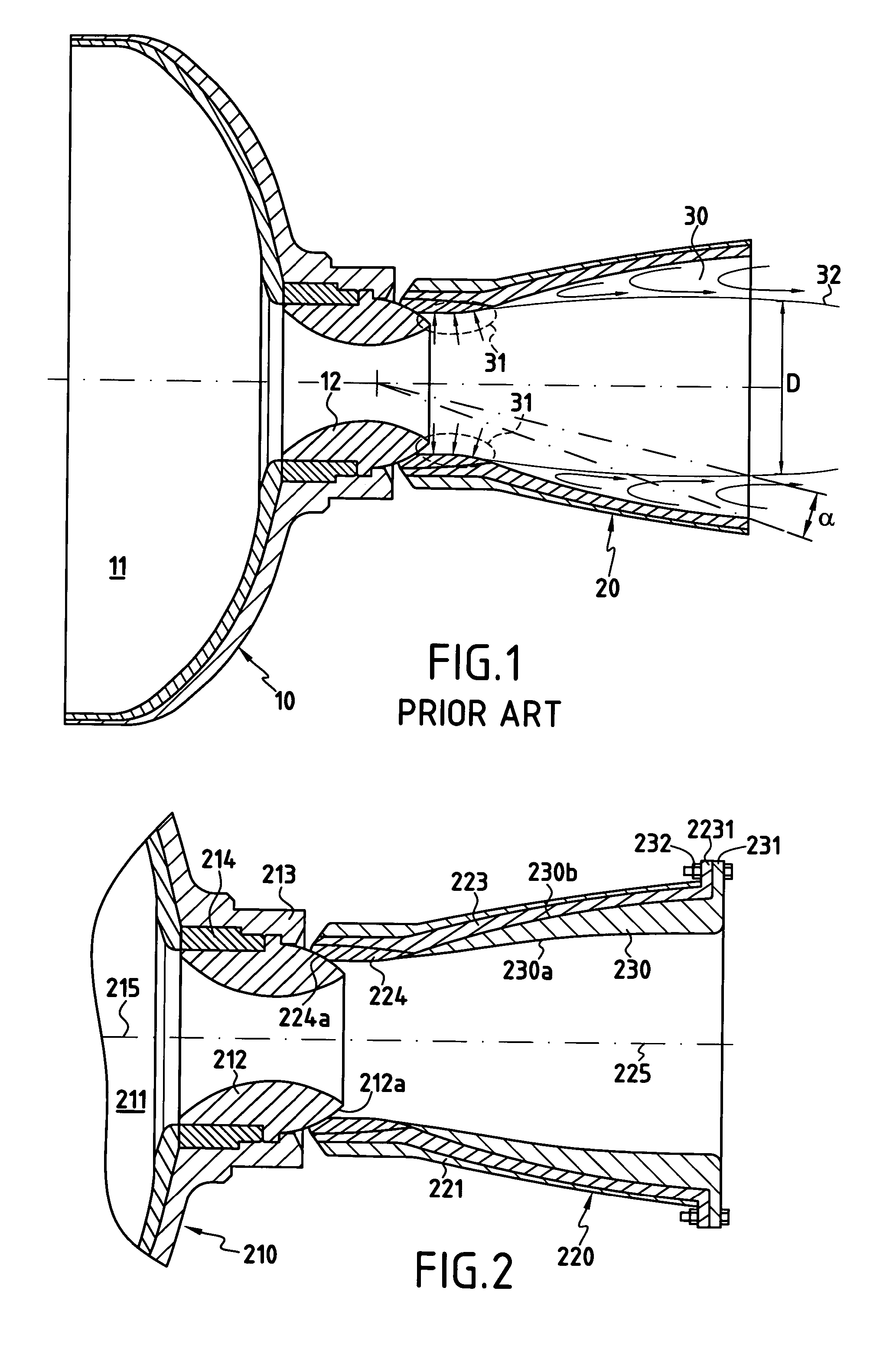
[0025]FIG. 2 is a highly diagrammatic view of the rear portion of a rocket engine comprising a casing 210 surrounding a combustion chamber 211 in which a block of solid propellant (not shown) is housed. The chamber 211 opens out through its rear end wall 213 at the front of a nozzle comprising a throat 212 and a diverging portion 220.

[0026]The throat 212 which defines not only the throat proper of the nozzle, but also its converging portion and the beginning of its diverging portion, is stationary, for example it is screwed into a ring 214 secured to the end wall 213 of the casing so as to be secured to the end wall 213.

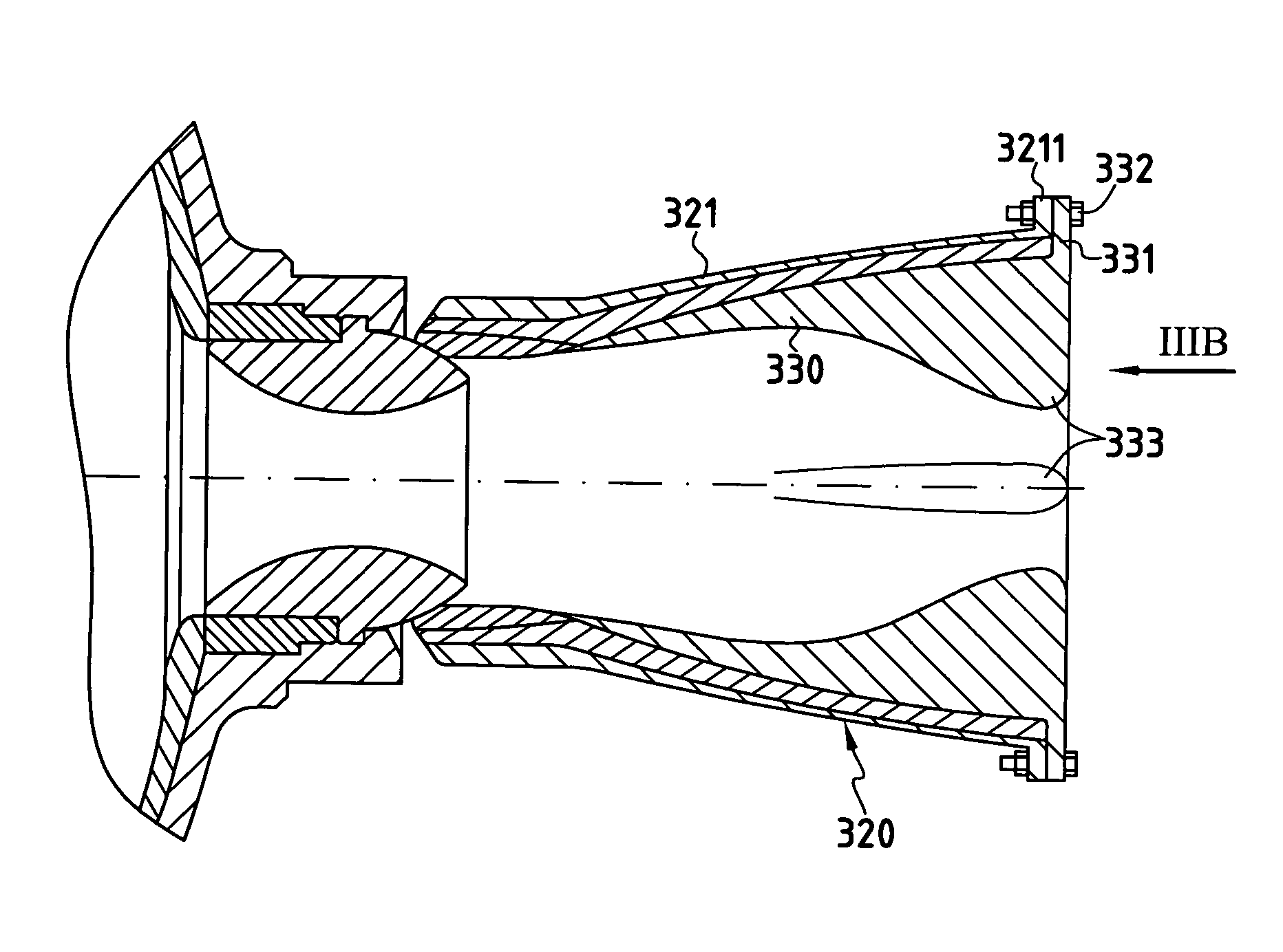
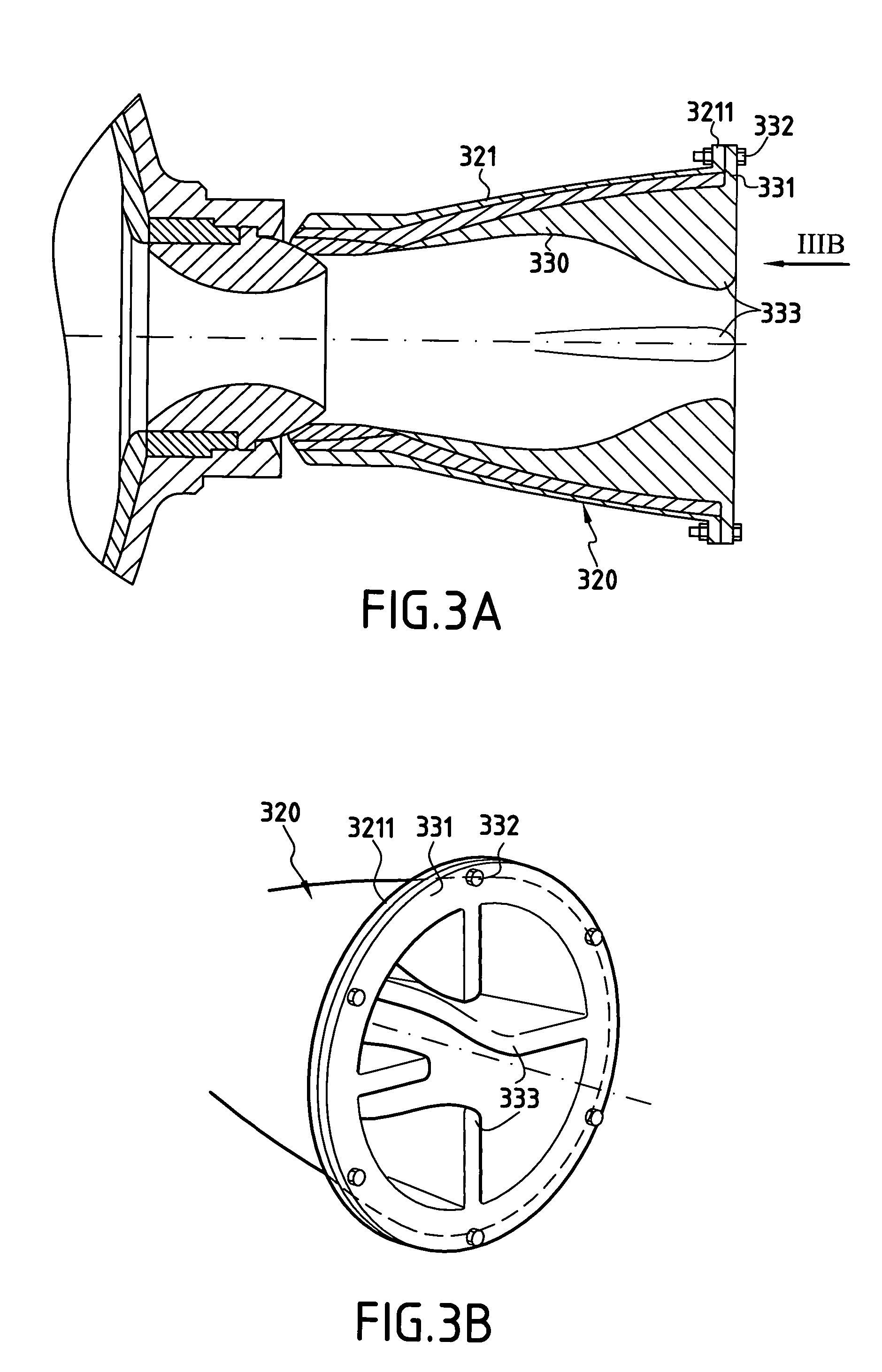
[0027]The diverging portion 220 of the nozzle is mounted movably on the nozzle throat 212, which is itself secured to the casing 210. Typically, the moving diverging portion comprises a casing 221, e.g. in the form of a metal carrying an inside layer 223 of insulating material such as an ablative composite material, e.g. made up of carbon or silica reinforcement and ...


PUM


Abstract

An adapter device for controlling a rocket engine nozzle under conditions of external pressure that can lead to the jet separating inside the nozzle, the nozzle being fitted with a diverging portion that is movably mounted relative to a stationary portion of the nozzle, thrust deflection then being achieved by swivelling the diverging portion so as to deflect the jet of combustion gas in contact with the inside wall of the diverging portion. The device includes a structure disposed inside the diverging portion in such a manner as to reduce the diverging nature of the flow section thereof and to increase the bearing area of pressure forces exerted by the jet on the diverging portion during swivelling thereof.

Description

[0001]This application claims priority to a French application No. 03 14454 filed Dec. 10, 2003.BACKGROUND OF THE INVENTION[0002]The present invention relates to steerable nozzles for rocket engines. The field of application of the invention is more particularly, but not exclusively, that of missiles, in particular tactical missiles having a diameter of less than about 500 millimeters (mm) and intended for operation under varying conditions of external pressure. A typical example of such a missile is a tactical missile launched from a submarine. The missile is ignited at great depth (about 150 meters (m)) and terminates its operational lifetime in the atmosphere after it has followed a determined trajectory obtained by controlling its nozzle(s).[0003]The technology that makes use of a moving diverging portion for steering thrust presents numerous advantages compared with other known technologies for steering thrust such as those using a steerable nozzle on a flexible abutment, for e...

Claims


Application Information

Patent Timeline
Patent Type & Authority Patents(United States)
IPC IPC(8): F02K1/00F02K1/78F02K9/84F02K9/97
CPCF02K9/978F02K9/84
Inventor HERVIO, ANTOINE
Owner ROXEL FRANCE
Why Eureka
Try Eureka