Movable arm and design method of movable arm

a technology of movable arms and design methods, which is applied in the field of movable arms, can solve the problems of shortened life span of movable arms and users rotating the movable bodies, and achieve the effect of reducing wear or reducing wear influence and exhibiting durability

Inactive Publication Date: 2007-06-28
MATSUSHITA ELECTRIC WORKS LTD
View PDF7 Cites 3 Cited by
  • Summary
  • Abstract
  • Description
  • Claims
  • Application Information

AI Technical Summary

Benefits of technology

[0005]It is, therefore, an object of the present invention to provide a movable arm that the life span is extended and a method of designing the same.
[0013]In accordance with the first aspect of the present invention, the position of the movable body relative to the base is maintained by the elastic force of the restoring body regardless of the frictional force. This makes it possible to eliminate or to reduce the influence of wear, causing the movable arm to exhibit a greater life span than in the case where the position of the movable body is maintained by the frictional force.
[0015]Consequently, it is possible to reduce the frictional force acting between the base and the movable body, thereby decreasing the power required for operating the movable body.
[0018]As a result, the position of the movable body relative to the base is maintained by the elastic force of the restoring body regardless of the frictional force. This helps to eliminate or reduce the influence of wear, making it possible for the movable arm to exhibit durability for a greater period of life span than that of the case where the position of the movable body is maintained by the frictional force.

Problems solved by technology

Moreover, since contact parts between the movable body and the base are worn each time the movable body is displaced with respect to the base.
Therefore, sooner or later, no frictional force acts between the movable body and the base, which makes it impossible for the movable body to be kept at a fixed position; or the movable body may be caused to extend awry and is caught against movement, which makes it difficult for the user to rotate the movable body, resulting in shortened life span of the movable arm.

Method used


Image

  • Movable arm and design method of movable arm
  • Movable arm and design method of movable arm
  • Movable arm and design method of movable arm

Examples


Embodiment Construction

[0027]Preferred embodiments of the present invention will now be described with reference to the accompanying drawings.

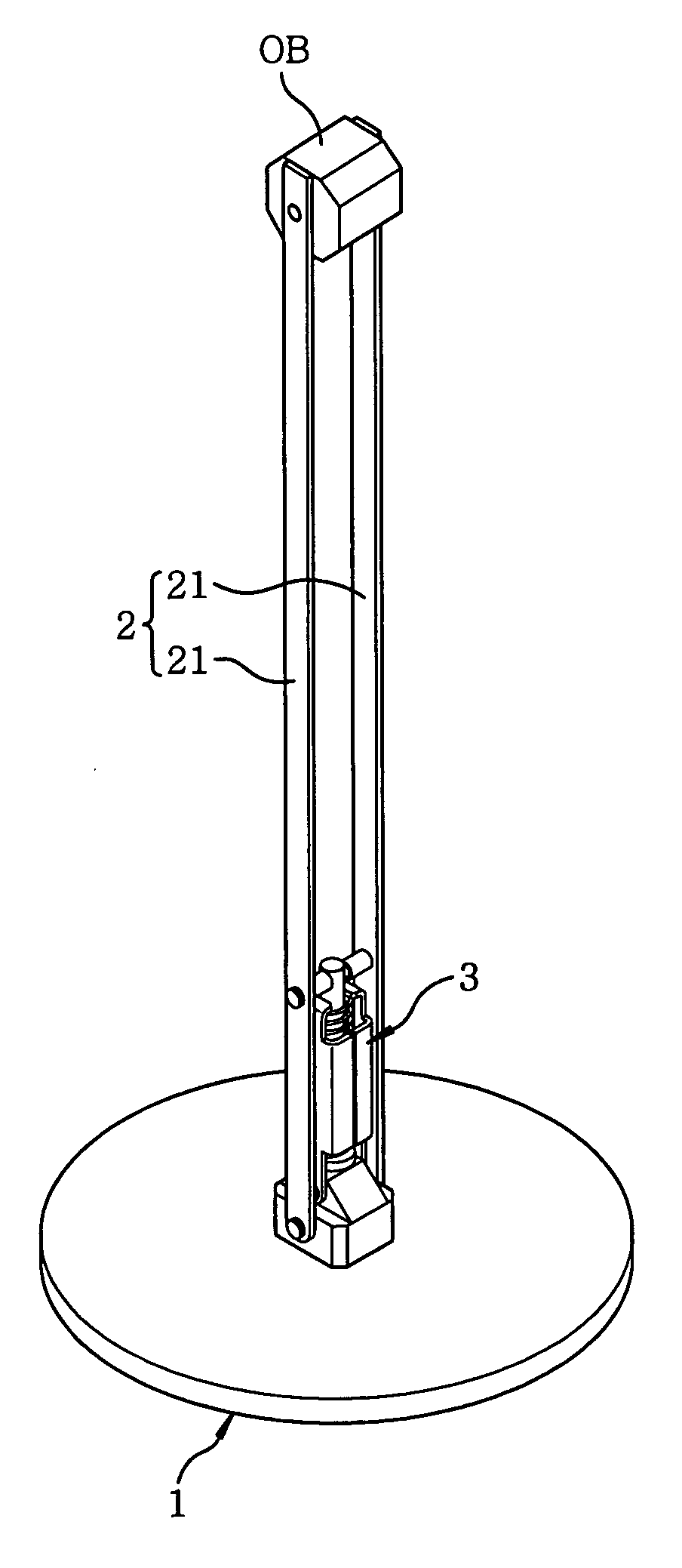
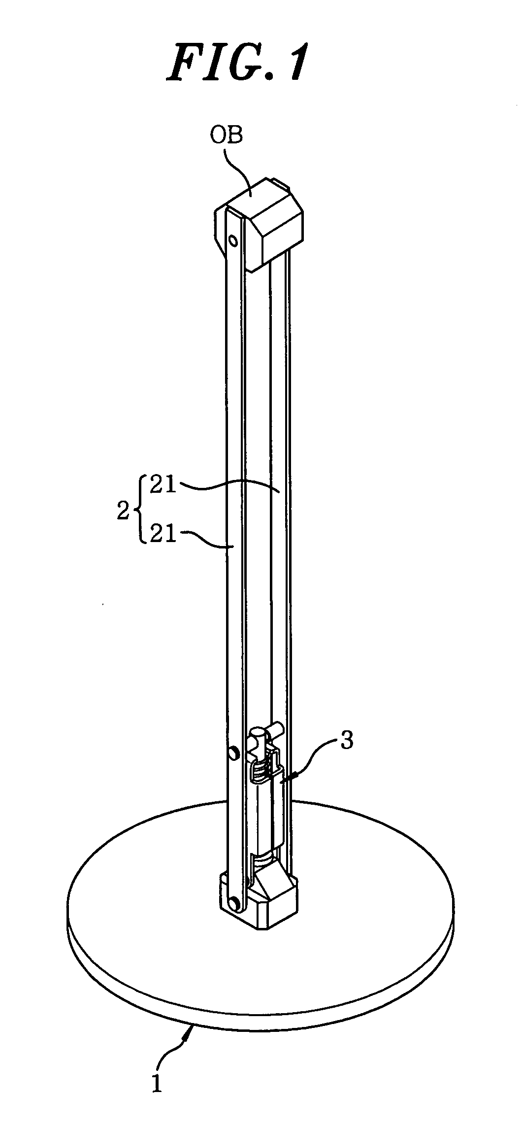
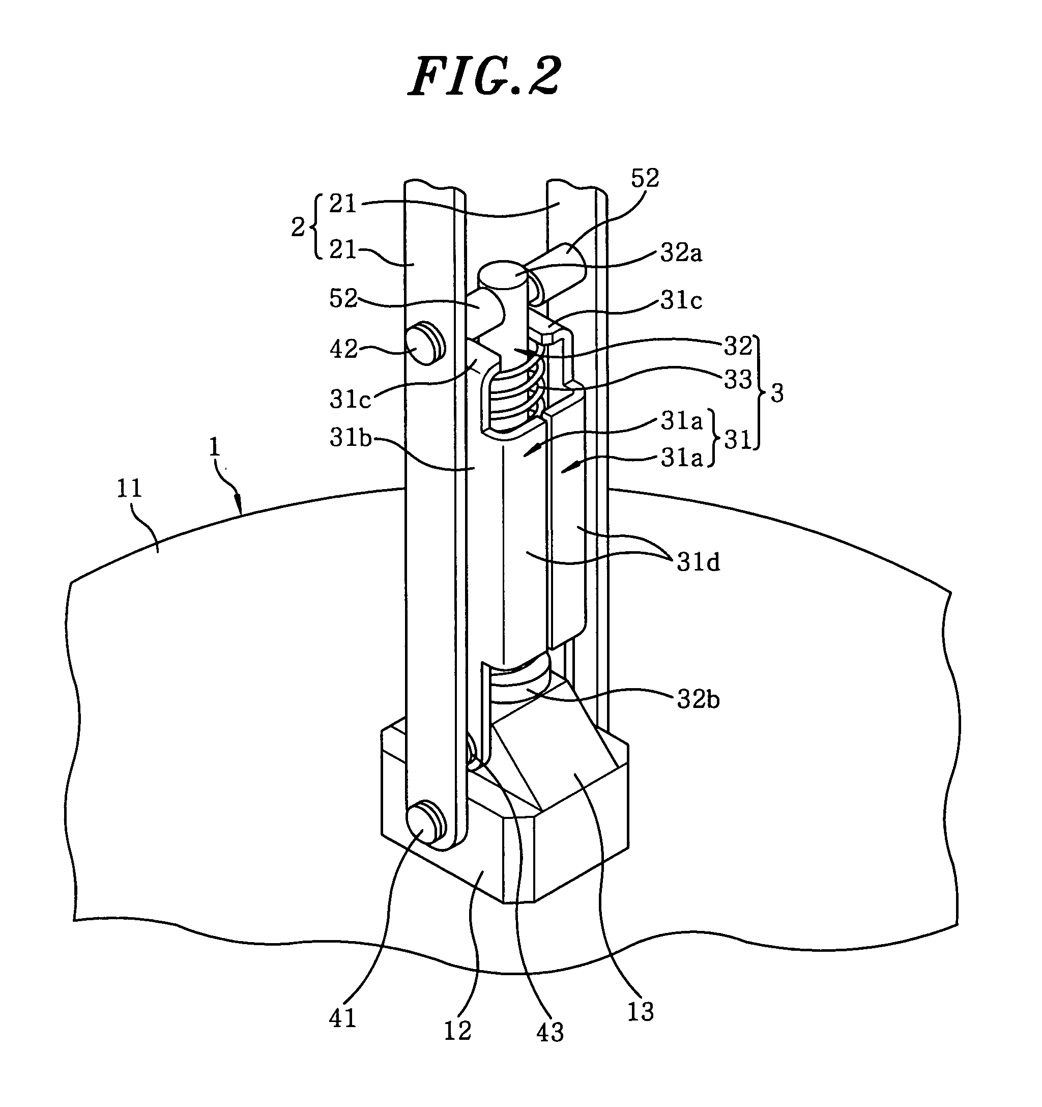
[0028]In the embodiment shown in FIG. 1, a movable arm includes a base 1 placed on a floor surface serving as a mounting surface; a movable body 2 having one end portion pivotally attached to the base 1 for rotation within a plane normal to the floor surface and the opposite end portion to which an object OB to be supported, e.g., a lighting fixture, is attached; and a restoring body 3 pivotally attached to the base 1 at a location upper than a pivot axis of the movable body 2 and also pivotally attached to the movable body 2 at a location closer to the object OB than the pivot axis of the movable body 2, the restoring body 3 rotating within the common plane on which the movable body 2 rotates. Hereinbelow, a “top-bottom direction” is defined on the basis of FIG. 1. The direction extending from the left top to the right bottom in FIG. 1 is referred to as a “left-rig...


PUM


Abstract

A movable arm includes a base secured to a mounting surface; a movable body pivotally attached to the base to rotate about the base and carrying an object; and a restoring body for biasing the movable body to a home position. An elastic modulus of the restoring body, a deformation amount of the restoring body in the home position and dimensions of individual parts are determined to ensure that the gravity acting on the movable body and the biasing force exerted by the restoring body are balanced regardless of the position of the movable body. Therefore, the position of the movable body can be maintained by the elastic force of the restoring body regardless of the frictional force and thus the movable arm is hardly affected by the wear, attaining a greater life span than in a case of maintaining the movable body by the frictional force.

Description

FIELD OF THE INVENTION[0001]The present invention relates to a movable arm for supporting an object such as a lighting fixture or the like and a method of designing the same.BACKGROUND OF THE INVENTION[0002]Conventionally, use has been made of a movable arm that includes a base fixedly secured to a mounting surface and a movable body having one end portion pivotally attached to the base and an opposite end portion to which an object to be supported is attached. The movable arm is adapted to support the object, e.g., a lighting fixture or a camera, such that the object can be freely movable with respect to the mounting surface.[0003]In the conventional movable arm, the position of the movable body relative to the base is maintained by the frictional force acting between the movable body and the base (see, e.g., Japanese Patent Publication No. H6-42323)[0004]Moreover, since contact parts between the movable body and the base are worn each time the movable body is displaced with respec...

Claims


Application Information

Patent Timeline
Patent Type & Authority Applications(United States)
IPC IPC(8): F16M11/00
CPCF16M11/04F16M11/2021F16M2200/044F16M2200/068
Inventor MIYASAKI, HIROSHI
Owner MATSUSHITA ELECTRIC WORKS LTD
Why Eureka
Try Eureka