Reciprocable member with anti-float arrangement

a technology of anti-float arrangement and reciprocating member, which is applied in the direction of valve arrangement, machines/engines, mechanical equipment, etc., can solve the problems of limiting engine braking power, valve seat wear due to uncontrolled valve closing, and damage to the valvetrain, so as to reduce the problem of valve float, high service cost, and high precision requirements

Active Publication Date: 2011-12-20
VOLVO LASTVAGNAR AB
View PDF12 Cites 3 Cited by
  • Summary
  • Abstract
  • Description
  • Claims
  • Application Information

AI Technical Summary

Benefits of technology

[0002]Exhaust manifold pressure has historically been one of the major design constraints for engine brakes that limit engine braking power. This is especially the case on single-valve actuation engine brakes, where only one exhaust valve spring is available to control exhaust valve motion during engine braking. In combination with valvetrain acceleration in the ‘closing’ direction, high exhaust manifold pressure during engine braking can cause the valve to ‘float’, or not follow the cam profile over the closing flank of the valve lift profile, producing the potential of piston-to-valve contact, valve seat wear due to uncontrolled valve closing, and valvetrain damage due to impact stresses. Valve float can generally be thought of as meaning unintended, uncontrolled motion of the valve. In extreme cases, high exhaust manifold pressure spikes have been known to ‘blow’ the exhaust valves off their seats during the intake stroke, causing unintended valve lift and, again, uncontrolled valve seating. This invention is for the purpose of reducing or eliminating the influence of exhaust manifold pressure on valve float.
[0004]Solutions to problems with valve float such as valve heads being struck by pistons include desmodromic valves that are positively closed by a cam and leverage system. Disadvantages to such systems include their high service costs and frequent service requirements needed as the result of high precision requirements.
[0005]It is desirable to provide an exhaust valve arrangement that reduces problems with valve float. It is also desirable to provide a valve arrangement for use in other applications that can reduce problems with valve float. It is also desirable to provide a valve arrangement that can reduce problems with valve float with minimal extra cost and requiring minimal additional servicing.

Problems solved by technology

Exhaust manifold pressure has historically been one of the major design constraints for engine brakes that limit engine braking power.
In combination with valvetrain acceleration in the ‘closing’ direction, high exhaust manifold pressure during engine braking can cause the valve to ‘float’, or not follow the cam profile over the closing flank of the valve lift profile, producing the potential of piston-to-valve contact, valve seat wear due to uncontrolled valve closing, and valvetrain damage due to impact stresses.
In extreme cases, high exhaust manifold pressure spikes have been known to ‘blow’ the exhaust valves off their seats during the intake stroke, causing unintended valve lift and, again, uncontrolled valve seating.
Whatever the application, valve float can be problematic.
Disadvantages to such systems include their high service costs and frequent service requirements needed as the result of high precision requirements.

Method used


Image

  • Reciprocable member with anti-float arrangement
  • Reciprocable member with anti-float arrangement
  • Reciprocable member with anti-float arrangement

Examples


Embodiment Construction

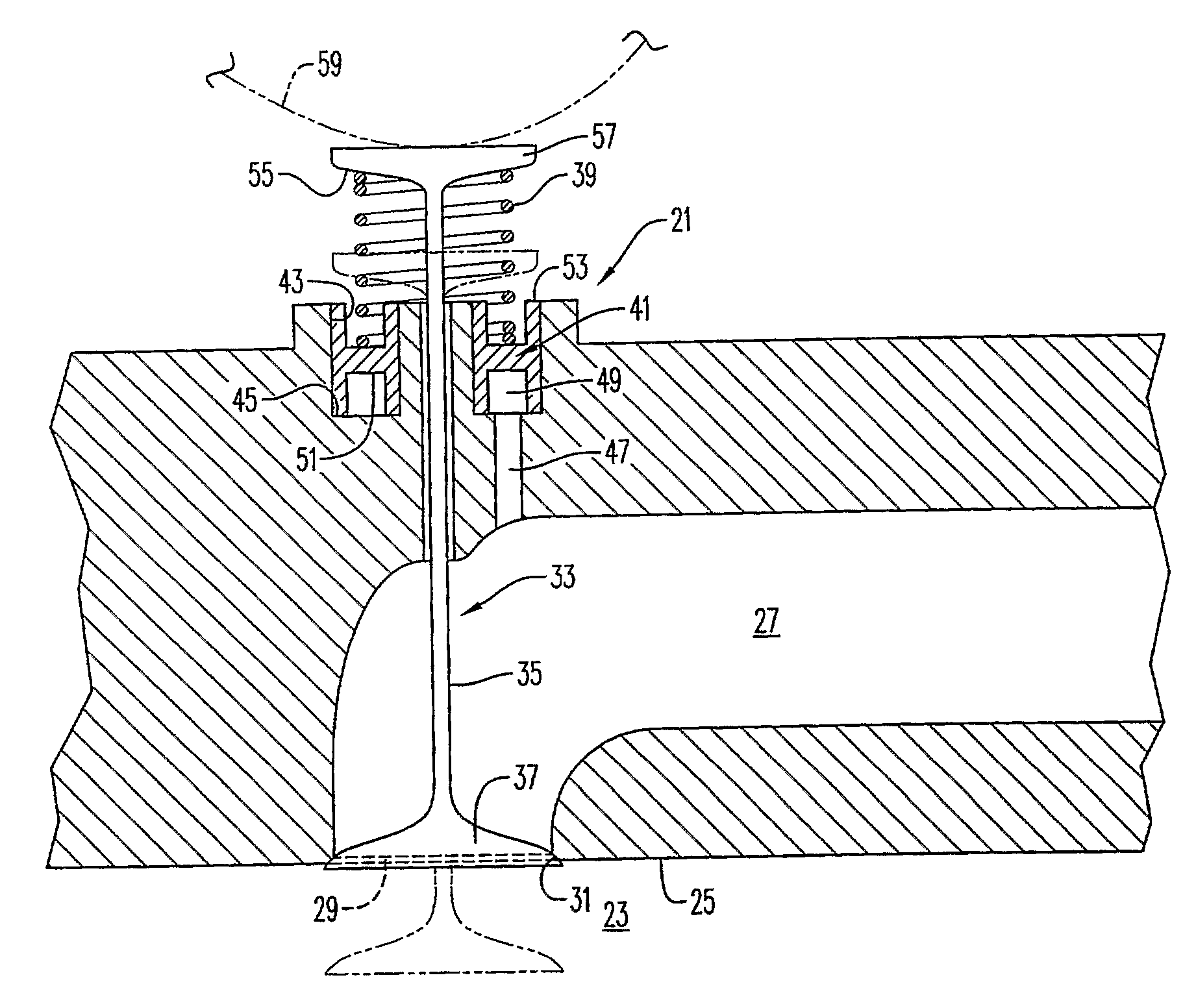
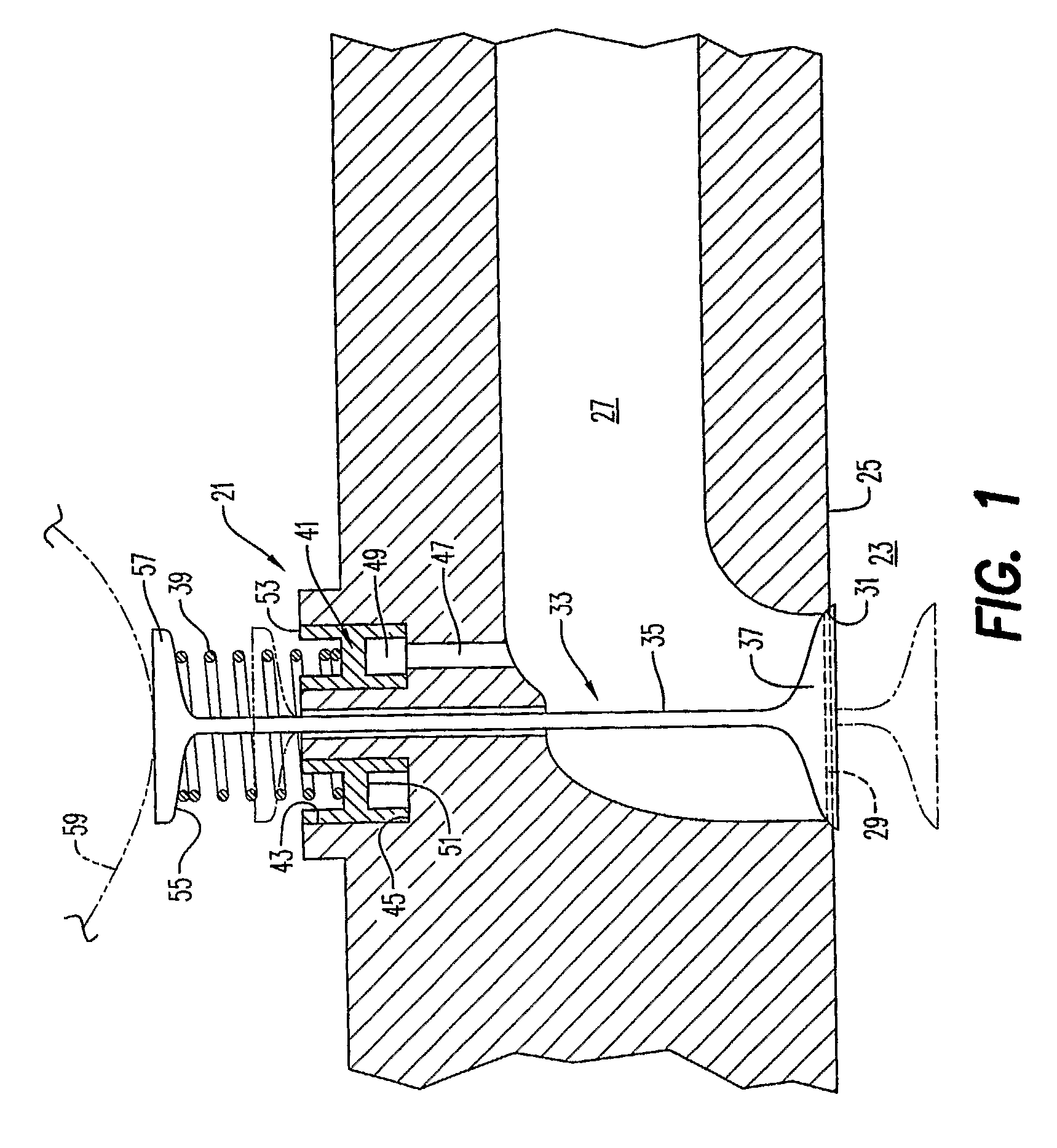
[0013]An exhaust valve arrangement 21 with an anti-float arrangement according to an embodiment of the present invention is shown in FIG. 1. While use of the present invention in conjunction with an exhaust valve arrangement is a possible application of the invention, it will be appreciated that the present invention has applications in other areas involving reciprocating members, as well. The exhaust valve arrangement 21 comprises a cylinder 23 having a top end 25. An exhaust conduit 27 is connected to the cylinder 23 by an opening 29 in the top end 25 of the cylinder. The opening 29 comprises a valve seat 31.

[0014]A valve member 33 comprising a valve stem 35 and a valve head 37 on the valve stem. The valve member 33 is movable between a closed position in which the valve head 37 is received in the valve seat 31 and an open position (shown in phantom) in which the valve head is spaced from the valve seat.

[0015]In the illustrated embodiment, the valve member 33 is ordinarily urged t...


PUM


Abstract

An exhaust valve arrangement includes a cylinder having a top end, an exhaust conduit connected to the cylinder by an opening in the top end of the cylinder, the opening comprising a valve seat, a valve member comprising a valve stem and a valve head on the valve stem, the valve member being movable between a closed position in which the valve head is received in the valve seat and an open position in which the valve head is spaced from the valve seat, and a resilient member arranged to urge the valve member to a closed position. A piston is mounted relative to the valve stem, the piston being disposed in a second cylinder in flow communication with the exhaust conduit and arranged such that a change in pressure in the exhaust conduit changes a degree of compression of the resilient member.

Description

BACKGROUND AND SUMMARY[0001]The present invention relates to reciprocable members and, more particularly, to reciprocable members such as valves with an anti-float arrangement.[0002]Exhaust manifold pressure has historically been one of the major design constraints for engine brakes that limit engine braking power. This is especially the case on single-valve actuation engine brakes, where only one exhaust valve spring is available to control exhaust valve motion during engine braking. In combination with valvetrain acceleration in the ‘closing’ direction, high exhaust manifold pressure during engine braking can cause the valve to ‘float’, or not follow the cam profile over the closing flank of the valve lift profile, producing the potential of piston-to-valve contact, valve seat wear due to uncontrolled valve closing, and valvetrain damage due to impact stresses. Valve float can generally be thought of as meaning unintended, uncontrolled motion of the valve. In extreme cases, high e...

Claims


Application Information

Patent Timeline
Patent Type & Authority Patents(United States)
IPC IPC(8): F01L3/10
CPCF01L1/46F01L1/462F01L1/465F01L13/06
Inventor SMITH, EDWARD M.
Owner VOLVO LASTVAGNAR AB
Why Eureka
Try Eureka