Development apparatus and image forming apparatus

a development apparatus and image forming technology, applied in the field of development apparatus, can solve the problems of affecting the discharge performance of developers, affecting the development of carriers with time, and affecting the development of carriers, so as to stabilize the amount of developers in the development apparatus to a certain level, stable development performance, increase and decrease the effect of developer amoun

Active Publication Date: 2011-07-05
KONICA MINOLTA BUSINESS TECH INC
View PDF10 Cites 3 Cited by
  • Summary
  • Abstract
  • Description
  • Claims
  • Application Information

AI Technical Summary

Benefits of technology

[0015]An object of the present invention is to achieve stable development performance in a development apparatus of a trickle system in an image forming apparatus of an electrophotographic system, by stabilizing the circulation performance of developer in the development apparatus, with a simple configuration and thereby stabilizing the amount of developer in the development apparatus to a certain level.
[0017]The development apparatus according to the first aspect is of a trickle system in which developer is caused to circulate in the developer tank by the first and second developer transport members, a part of the developer is discharged by the developer discharging mechanism, and developer is replenished from the developer replenishing portion. In the developer discharging mechanism, a force that discharges developer and a force that restricts the discharge of developer are present. However, by making a transport force acting on developer at the first passing portion adjacent to the developer discharging mechanism greater than a transport force acting on developer acting on developer at the second passing portion provided away from the developer discharging mechanism, the influence exerted on a developer transport force by the force that discharges developer and the force that restricts the discharge of developer which are present in the developer discharging mechanism can be eliminated or reduced. As a result, the circulation performance of developer in the development apparatus is stabilized, enabling to stabilize the amount of developer in the development apparatus to a certain level.
[0021]According to the development apparatus of the present invention, the circulation performance of developer in the development apparatus is stabilized, enabling to stabilize the amount of developer in the development apparatus to a certain level. By suppressing an increase and decrease in the amount of developer in the development apparatus, image loss or an insufficient supply of toner due to an insufficient amount of developer, or a local image overlap or an insufficient toner density resulting from a developer circulation failure due to an excess of developer can be eliminated or suppressed, enabling to achieve stable development performance.

Problems solved by technology

However, in a conventional two-component development system in which an amount of toner corresponding to an amount of toner consumed by development is replenished without discharging any developer from a development apparatus, degradation of carrier that develops with time is problematic.
However, the so-called trickle system has another problem that does not arise in the conventional two-component development system.
Specifically, near the developer discharging mechanism, due to the influence of these discharge force and blocking force, circulation performance is weakened as compared with that on the other side of the developer discharging mechanism.
Also, a change in circulation performance brought about by a change in the speed of the development apparatus leads to a change in the developer discharge performance of the developer discharging mechanism, which similarly causes variation in the amount of developer in the development apparatus.
A decrease in the amount of developer in the development apparatus leads to a decrease in the amount of developer supplied to a developer carrying member, which in turn causes problems such as image loss and a developer supply failure.
On the other hand, an increase in the amount of developer in the developer apparatus causes stagnation of circulation of the developer in the development apparatus, which in turn causes problems such as insufficient stirring of developer and a developer supply failure.
The configurations disclosed in Japanese Patent Application Laid-open Publication No. 2006-323238, however, have the following problems.

Method used


Image

  • Development apparatus and image forming apparatus
  • Development apparatus and image forming apparatus
  • Development apparatus and image forming apparatus

Examples


first embodiment

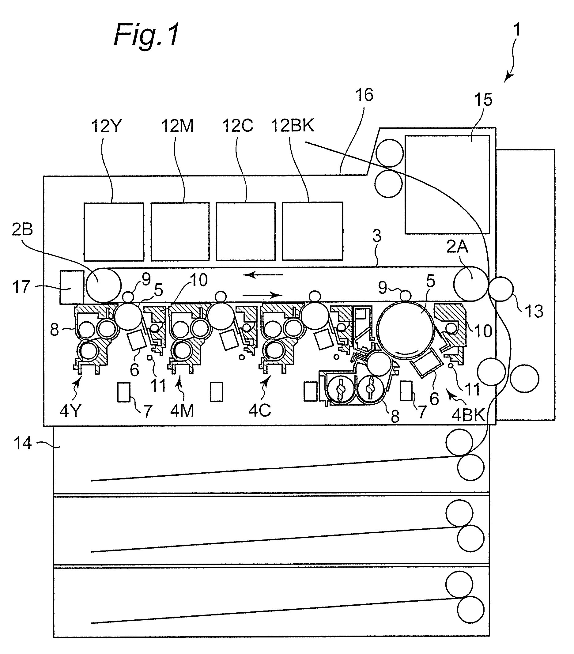
[0041]FIG. 1 is a diagram showing a tandem-type color image forming apparatus 1 to which electrophotographic technology is applied, according to the present embodiment. Note, however, that the application of the present invention is not limited to the image forming apparatus 1 of this type; for example, the present invention can also be applied to color image forming apparatuses and monochrome output image forming apparatuses of a so-called four cycle system. Also, the present invention can be applied to copiers, printers, and facsimile machines and multifunction products having functions thereof in combination.

[0042]The image forming apparatus 1 includes an intermediate transfer belt 3 that is wound around a pair of rollers 2A and 2B and rotatedly driven counterclockwise in the drawing.

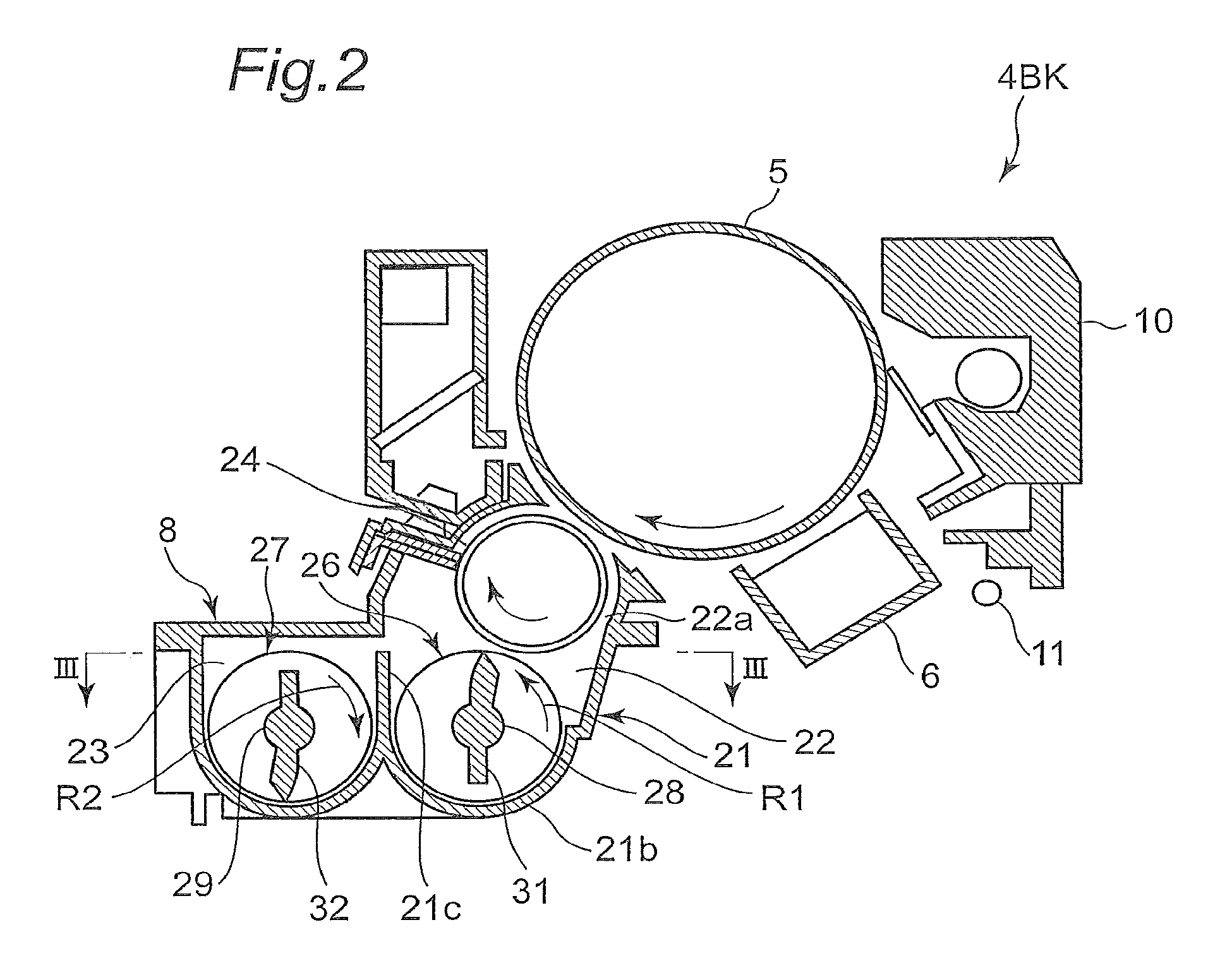
[0043]Under a lower horizontal portion of the intermediate transfer belt 3, four image forming units 4Y, 4M, 4C, and 4BK respectively corresponding to yellow (Y), magenta (M), cyan (C), and black (BK...

second embodiment

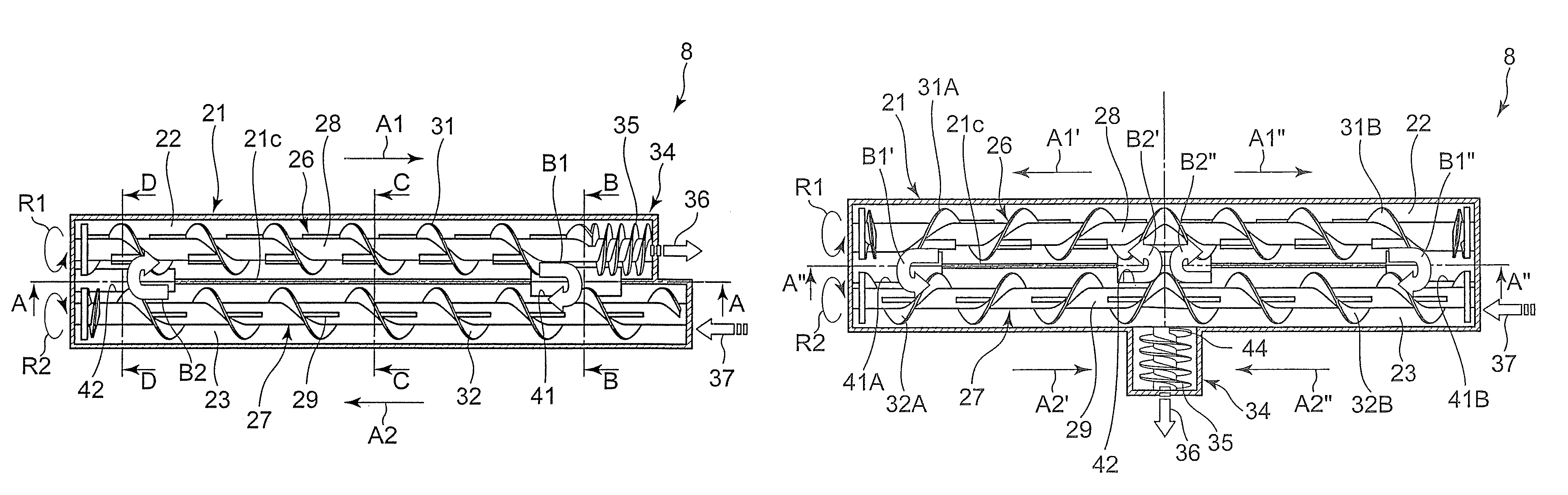
[0073]A development apparatus 8 according to a second embodiment of the present invention which is shown in FIGS. 7 and 8 is different from that according to the first embodiment in the structure of a developer discharging mechanism 34. Specifically, the developer discharging mechanism 34 according to the present embodiment includes a rotating shaft 43 extending in a direction orthogonal to a rotating shaft 28 of a developer transport member 26 and a spiral blade 35 is formed on the rotating shaft 43. That is, in the present embodiment, the developer discharging mechanism 34 causes developer to be discharged in the direction orthogonal to a developer transport direction A1 of the developer transport member 26. A height H1 of a lower end of a passing portion 41 adjacent to the developer discharging mechanism 34 is set lower than a height H2 of a lower end of a passing portion 42 provided away from the developer discharging mechanism 34, whereby the circulation performance of develope...

third embodiment

[0075]A development apparatus 8 according to a third embodiment of the present invention which is shown in FIGS. 9 and 10 is different from that according to the first embodiment in the mode of a developer circulation path in a developer tank 21.

[0076]A developer transport member 26 includes spiral blades 31A and 31B oriented in different directions and provided on the left and right sides in FIG. 9 from the center in a length direction of a rotating shaft 28. The spiral blades 31A and 31B are connected to each other on the center in the length direction of the rotating shaft 28. The developer transport member 26 transports developer from the center in the length direction to both ends. Specifically, while, as shown by an arrow A1′, developer is transported by the spiral blade 31A from the center in the length direction to a left end in the drawing, as shown by an arrow A1″, developer is transported by the spiral blade 31B from the center in the length direction to a right end in th...


PUM


Abstract

A development apparatus 8 has developer transport members 26 and 27 respectively contained in containers 22 and 23 and transporting developer while stirring the developer and passing the developer to each other at a passing portion 41 and a passing portion 42, thereby causing the developer to circulate in a developer tank 21. The passing portion 41 is formed at a location of a partition 21c adjacent to a developer discharging mechanism 34 and the passing portion 42 is formed at a location of the partition 21c away from the developer discharging mechanism 34. The passing portions 41 and 42 have configurations in which a transport force acting on the developer at the passing portion 41 is greater than the transport force acting on the developer at the passing portion 42.

Description

RELATED APPLICATION[0001]This application is based on Japanese Patent Application No. 2008-160471, the contents of which are incorporated herein by reference.BACKGROUND OF THE INVENTION[0002]The present invention relates to a development apparatus in image forming apparatuses of an electrophotographic system, including copiers, printers, facsimile machines, and multifunction products thereof.[0003]In a processing apparatus, such as a development apparatus, included in an image forming apparatus of an electrophotographic system, particularly with an increase in full-color output, there are demands for an extension of life, an increase in reliability, and an improvement in image quality in addition to miniaturization of the apparatus and an increase in output.[0004]In the development apparatus, a so-called two-component development system in which developer having toner and carrier mixed therein is used is the mainstream. In the two-component development system, by continuously replen...

Claims


Application Information

Patent Timeline
Patent Type & Authority Patents(United States)
IPC IPC(8): G03G15/08
CPCG03G15/0877G03G15/0893G03G2215/0822G03G2215/0833G03G2215/0838
Inventor OKAZAKI, FUTOSHISAKAMOTO, KAZUHIRO
Owner KONICA MINOLTA BUSINESS TECH INC
Why Eureka
Try Eureka