Optical disk recording method and optical disk recording apparatus

a recording method and optical disk technology, applied in the field of optical disk recording methods and optical disk recording apparatuses, can solve the problems of phase shift correction failure and pre-rate failure, and achieve the effect of reducing or eliminating the influence of crosstalk

Inactive Publication Date: 2010-12-28
SONY CORP
View PDF9 Cites 3 Cited by
  • Summary
  • Abstract
  • Description
  • Claims
  • Application Information

AI Technical Summary

Benefits of technology

[0014]It is therefore desirable to provide an optical disk capable of high-speed processing and having multiple recording layers, which does not depend on the quality of a pre-pit signal during recording.
[0022]According to an embodiment of the present invention, when a first reference clock signal used for recording is generated on the basis of a wobble signal, a second reference clock signal is generated on the basis of a pre-pit signal, and an amount of phase shift of the first reference clock signal is detected on the basis of the second reference clock signal. An average value of the detected amount of phase shift is used to correct the first reference clock signal, whereby the first reference clock signal that is less affected by the influence of crosstalk can be generated. Therefore, the recording operation can be started without any influence of crosstalk, and can be ended without any influence of crosstalk.
[0023]In particular, data is recorded onto an optical disk using the first reference clock signal, and the first reference clock signal is corrected using the second reference clock signal before starting the recording of the data onto the optical disk using the first reference clock signal. Therefore, the influence of crosstalk can be eliminated or reduced even if a pre-pit signal fails to be detected during the recording of the data onto the optical disk.

Problems solved by technology

However, with the recent high-speed recording or reproduction or multiple recording layers, the read rate of the pre-pit signal may be lowered during or after the recording of predetermined data, resulting in failure of phase shift correction.

Method used


Image

  • Optical disk recording method and optical disk recording apparatus
  • Optical disk recording method and optical disk recording apparatus
  • Optical disk recording method and optical disk recording apparatus

Examples


Embodiment Construction

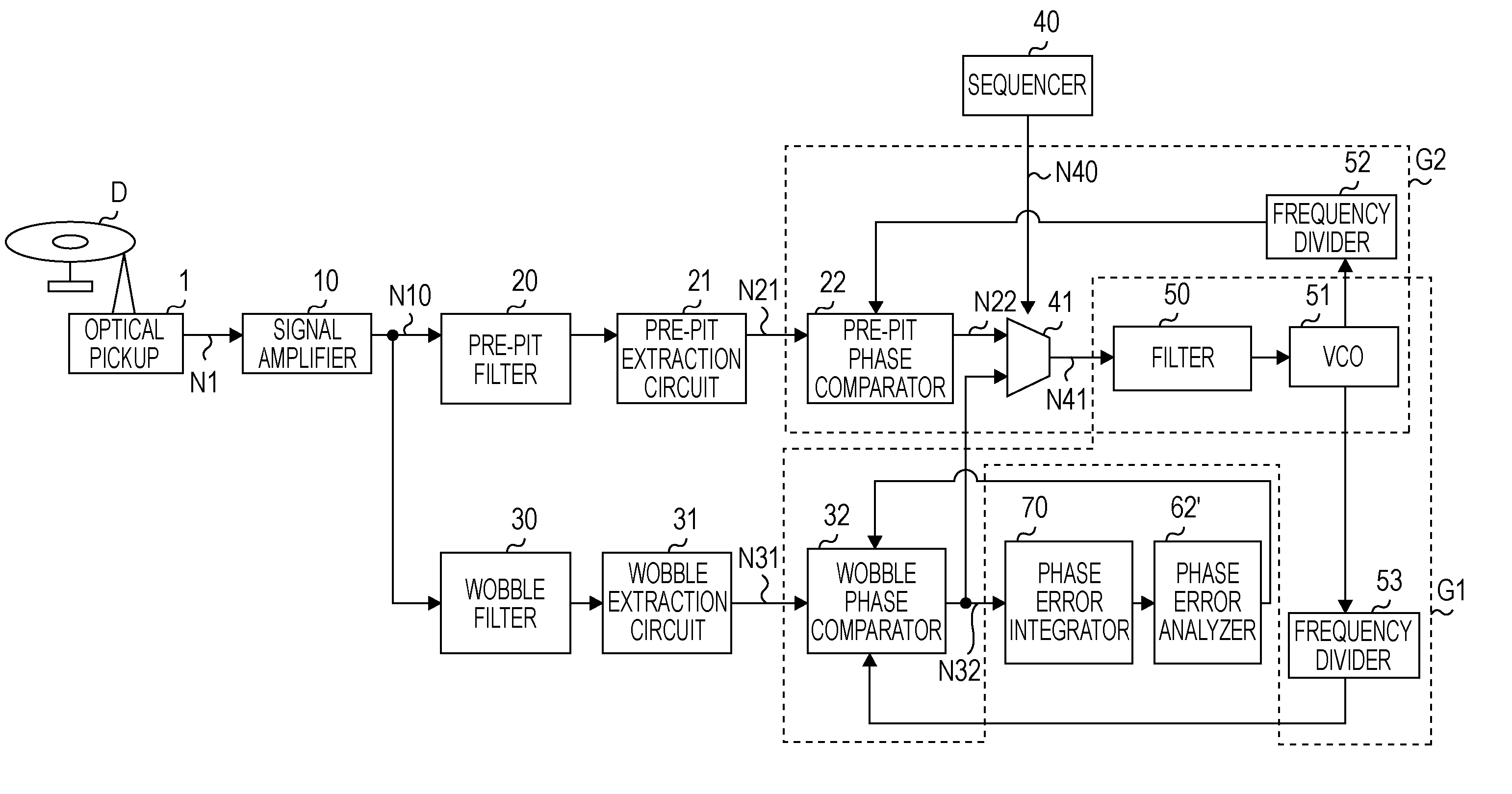
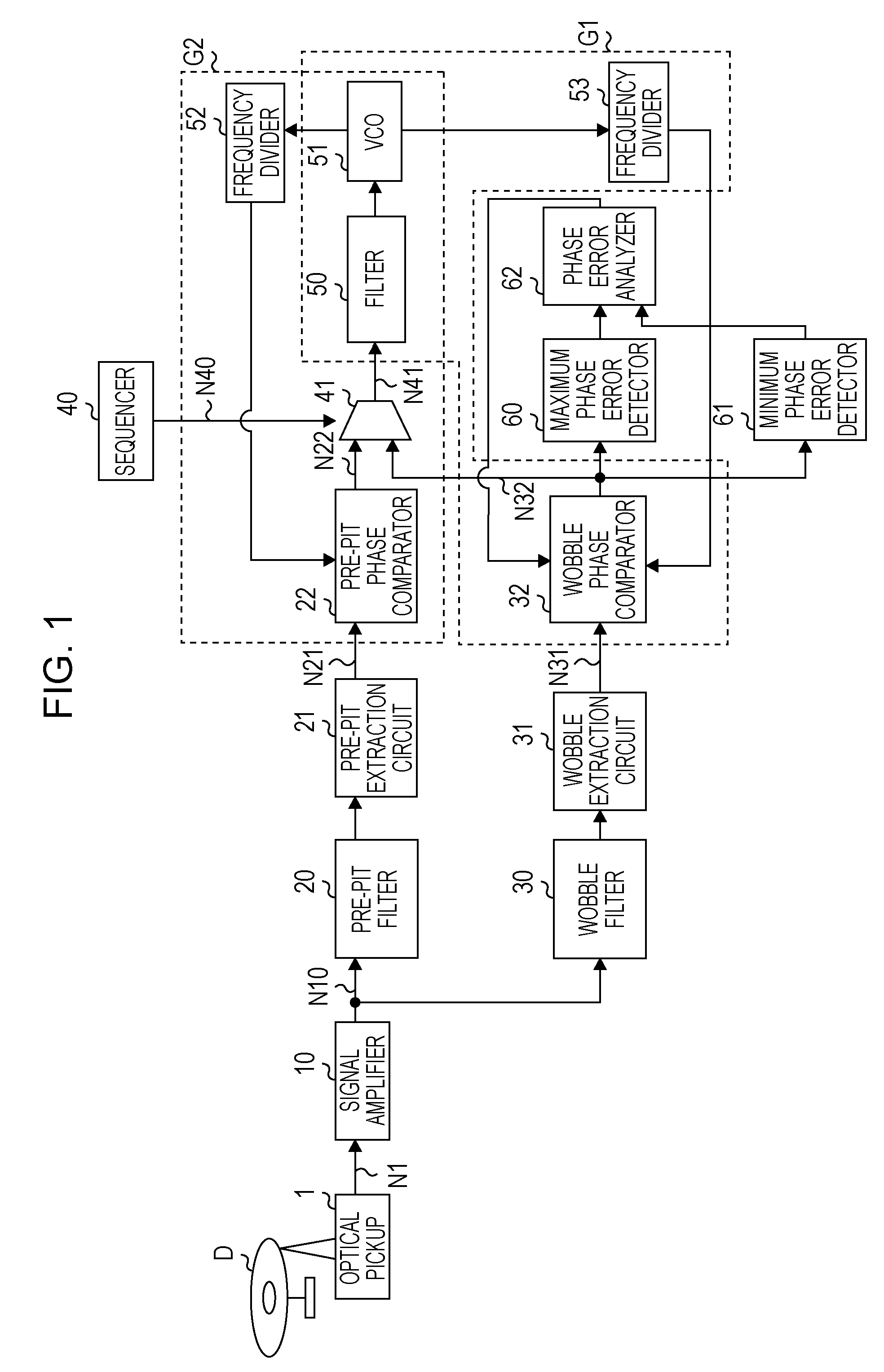
[0038]FIG. 1 is a schematic block diagram showing a system configuration of an optical disk recording apparatus according to an embodiment of the present invention.

[0039]The optical disk recording apparatus includes an optical pickup 1 that irradiates laser light onto an optical disk D serving as a recording medium to read the laser light reflected from a signal recording surface of the optical disk D. The optical pickup 1 outputs a wobble / pre-pit signal N1 including a wobble signal read from a groove track and a pre-pit signal read from a land track.

[0040]The wobble / pre-pit signal N1 is input to a signal amplifier 10. The signal amplifier 10 amplifies the wobble / pre-pit signal N1, and outputs an amplified wobble / pre-pit signal N10.

[0041]The amplified wobble / pre-pit signal N10 is input to a wobble filter circuit 30 for desired filtering processing. The amplified wobble / pre-pit signal N10 subjected to the filtering processing is input to a wobble extraction circuit 31 to extract a wo...


PUM

PropertyMeasurementUnit
phase shiftaaaaaaaaaa
phaseaaaaaaaaaa
radio-frequencyaaaaaaaaaa

Abstract

An optical disk recording method for recording predetermined data on an optical disk on the basis of a first reference clock signal used for recording, the optical disk including a groove track having a wobble signal recorded thereon and a land track having a land pre-pit carrying track position information, the first reference clock signal being generated on the basis of the wobble signal reproduced from the optical disk, includes the steps of reproducing a pre-pit signal from the optical disk; generating a second reference clock signal from the pre-pit signal; detecting an amount of phase shift of the first reference clock signal using the second reference clock signal; and correcting the first reference clock signal on the basis of an average value of the detected amount of phase shift.

Description

CROSS REFERENCES TO RELATED APPLICATIONS[0001]The present invention contains subject matter related to Japanese Patent Application JP 2006-196406 filed in the Japanese Patent Office on Jul. 19, 2006, the entire contents of which are incorporated herein by reference.BACKGROUND OF THE INVENTION[0002]1. Field of the Invention[0003]The present invention relates to optical disk recording methods and optical disk recording apparatuses. More specifically, the present invention relates to an optical disk recording method for recording data on an optical disk including a groove track on which a wobble signal is recorded and a land track having land pre-pits carrying track position information, and an optical disk recording apparatus.[0004]2. Description of the Related Art[0005]An optical disk such as a digital versatile disk-recordable / rewritable (DVD-R / RW) disk generally has, on a recording surface thereof, a groove track on which a wobble signal is recorded and a land track having land pre...

Claims


Application Information

Patent Timeline
Patent Type & Authority Patents(United States)
IPC IPC(8): G11B7/00
CPCG11B7/0053G11B7/00736G11B7/24082G11B20/1403G11B7/0045G11B7/24038G11B7/007
Inventor NAKASEKO, TETSUJIOSABE, HISAO
Owner SONY CORP
Why Eureka
Try Eureka