Adjustable dumbbell

a dumbbell and adjustable technology, applied in the field of adjustable dumbbells, can solve the problems of inconvenient and time-consuming adjustment of the conventional adjustable dumbbell b>10/b>

Inactive Publication Date: 2008-08-19
ASIA REGENT
View PDF20 Cites 51 Cited by
  • Summary
  • Abstract
  • Description
  • Claims
  • Application Information

AI Technical Summary

Problems solved by technology

As a result, adjustment of the conventional adjustable dumbbell 10 is inconvenient and time-consuming.

Method used


Image

  • Adjustable dumbbell
  • Adjustable dumbbell
  • Adjustable dumbbell

Examples


Embodiment Construction

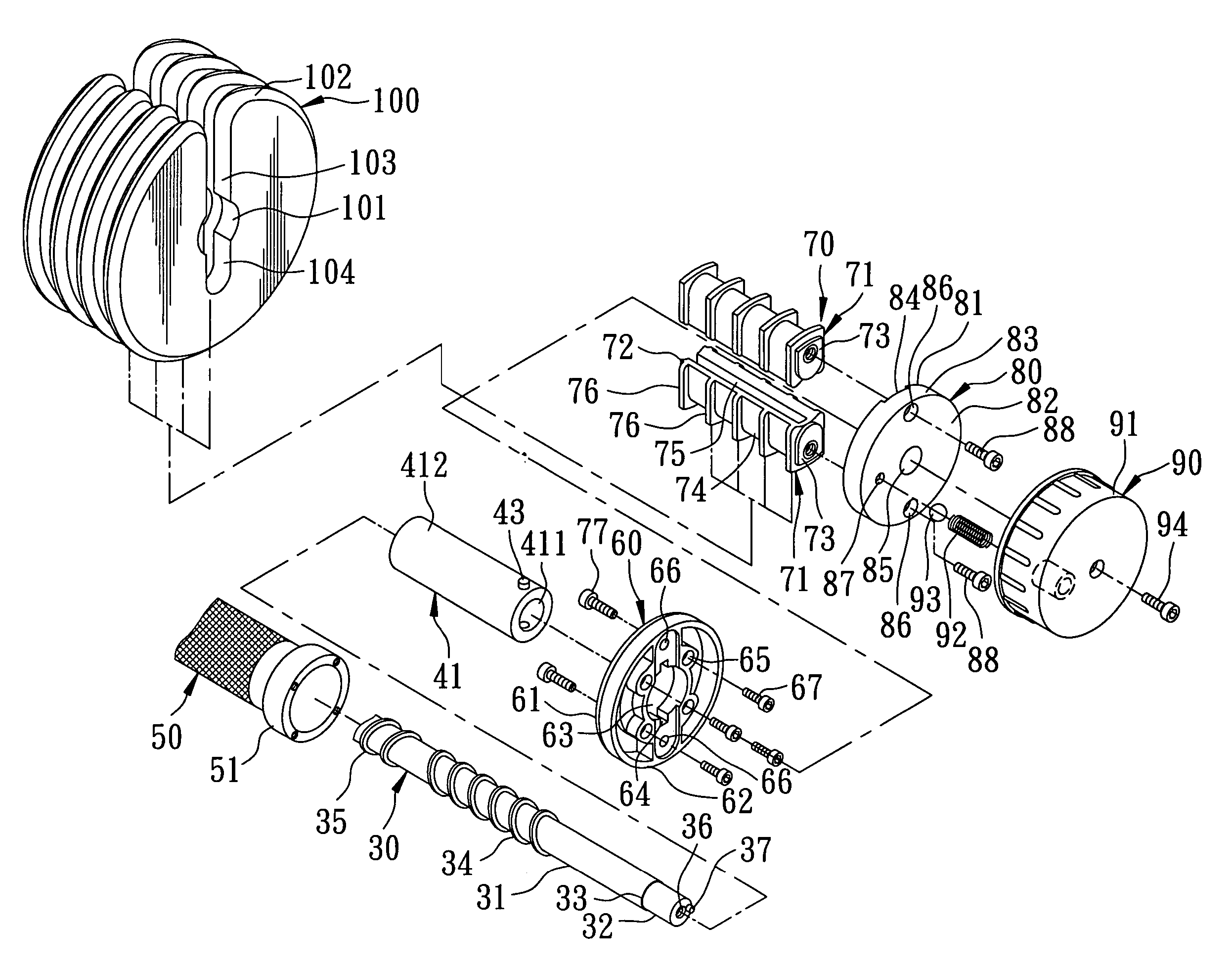
[0029]Referring to FIGS. 5 to 10, the preferred embodiment of an adjustable dumbbell according to the present invention is shown to comprise a shaft 30, two tubes 41, 42, a hollow grip rod 50, two first covers 60, two support units 70, two adjustment knob units 90, two sets of weights 100, and a base 110.

[0030]The shaft 30 includes two opposite connecting ends 32, an intermediate portion 31 between the connecting ends 32, two shoulder portions 33 each defined between the intermediate portion 31 and the corresponding connecting end 32, left- and right-handed threads 34, 35 that are formed on the intermediate portion 31 and that are axially spaced apart from each other, two screw holes 36 formed respectively in the connecting ends 32, and two eccentric projections 37 projecting axially, outwardly, and respectively from end faces of the connecting ends 32. The intermediate portion 31 has a diameter larger than those of the connecting ends 32.

[0031]The tubes 41, 42 are sleeved around an...


PUM


Abstract

An adjustable dumbbell includes a shaft provided with left- and right-handed threads, two tubes sleeved around and engaging threadedly and respectively the left- and right-handed threads, a hollow grip rod sleeved on the tubes, two support units each having upper and lower support seats disposed above and below one of the tubes, and a plurality of weights each having an engaging hole section engageable with a corresponding tube. Two adjustment knob units are respectively connected to two connecting ends of the shaft to turn the shaft and to thereby move the tubes in opposite directions towards or away from the connecting ends. Each tube is movable between the support seats to selectively engage one or more engaging hole sections of the weights.

Description

BACKGROUND OF THE INVENTION[0001]1. Field of the Invention[0002]The invention relates to exercise equipment, more particularly to an adjustable dumbbell.[0003]2. Description of the Related Art[0004]Referring to FIGS. 1 and 2, a conventional adjustable dumbbell 10, as disclosed in U.S. Pat. No. 6,656,093, includes a base 11 for supporting a plurality of weights 12, a rod 13, two latches 14, and two adjustable units 15.[0005]Each of the weights 12 includes a lateral channel 121, and a vertical groove 122 communicating with the lateral channel 121. The lateral channel 121 has a width greater than that of the vertical groove 122.[0006]The rod 13 has two blocks 132 provided respectively on two opposite ends thereof for engaging the vertical grooves 122 of the weights 12, and two conduits 133 laterally and respectively formed in the middle portions of the blocks 132. Each of the blocks 132 includes a passage 135 communicating with the respective conduit 133, and a plurality of spaced-apar...

Claims


Application Information

Patent Timeline
Patent Type & Authority Patents(United States)
IPC IPC(8): A63B21/072A63B21/075
CPCA63B21/075A63B21/00065
Inventor LIN, WILLIAM
Owner ASIA REGENT
Why Eureka
Try Eureka