
Balanced stackable dumbbell system

Inactive Publication Date: 2006-03-21
BALANCED BELLS +1
View PDF19 Cites 48 Cited by
  • Summary
  • Abstract
  • Description
  • Claims
  • Application Information

AI Technical Summary

Benefits of technology

[0006]Accordingly, it is an object of the present invention to provide a dumbbell system which is capable of providing several increments of weight in a compact construction.
[0007]It is another object of the present invention to provide a dumbbell system which provides equally distributed weight around the handle of the dumbbell assembly so that rotation of the handle away from a horizontal position does not result in undesirable added stresses on the user's wrist.
[0008]It is yet another object of the present invention to enable a user to attach a pair of dumbbells to a bar for use as a barbell. As a result the barbell maintains the incremental weight / compact construction advantages of the individual dumbbells.
[0010]A series of additional weight rings are adapted to be removably mounted to one another in order to provide variable increments of weight. The base weight member as well as the additional weight rings can be nested together in a single assembly and the lock rings can be selectively engaged or disengaged from the weight rings in order to allow the user to select from a plurality of weight increments. The lock rings can be provided with a plurality of dimples on a face surface thereof in order to facilitate rotation of the lock ring relative to the corresponding weight ring so that the lock ring can be easily engaged or disengaged from the weight ring.

Problems solved by technology

Because such sets of dumbbells are extremely expensive and consume a lot of space, these sets are not well designed for home use.
A problem with these prior art designs is that it is still necessary to maintain a full set of disc weights which can be placed on the ends of the dumbbell bar.
Furthermore, it is time consuming to put the weights on and take the weights off from this type of dumbbell design.
The locking collars are also a safety hazard if they are not properly secured in place.
In addition, with the weights being disposed at each end of the dumbbell, the moment arm which is applied to a user's wrist if the dumbbell is not maintained in a horizontal plane can result in painful stresses to the wrist joint of the user.
Similar painful stresses are present with standard one-piece dumbbells.

Method used


Image

  • Balanced stackable dumbbell system
  • Balanced stackable dumbbell system
  • Balanced stackable dumbbell system

Examples


Embodiment Construction

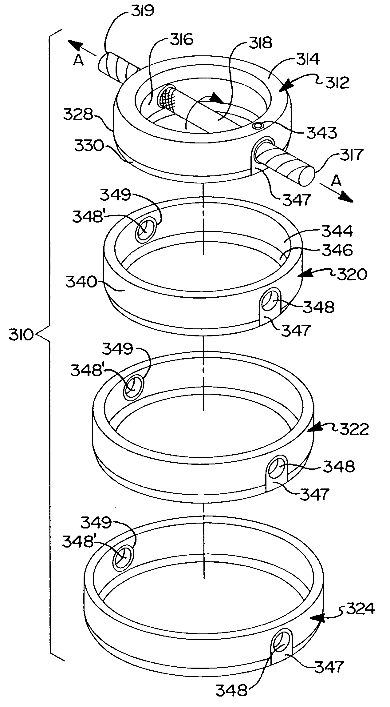
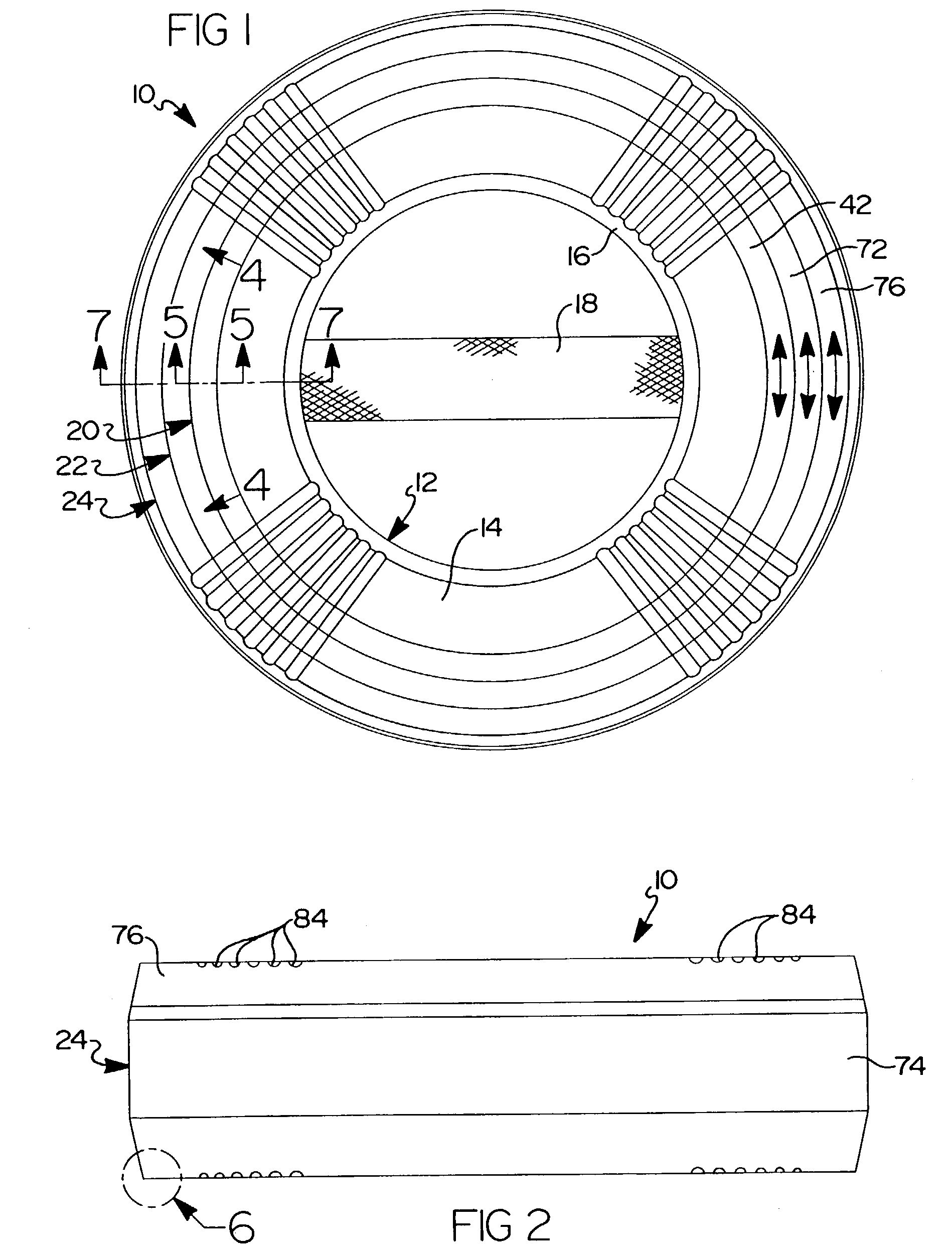
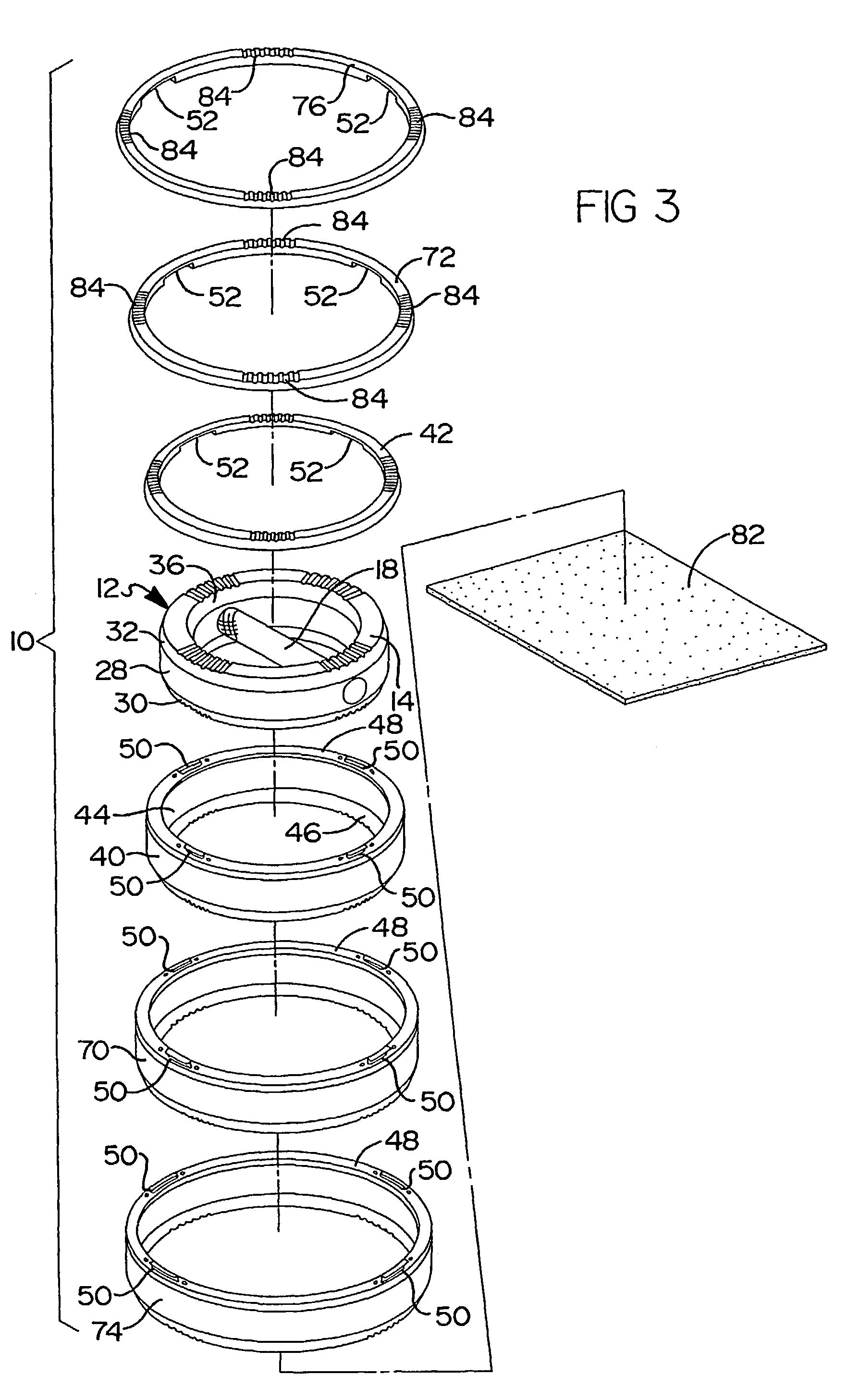
[0043]With reference to the accompanying drawings, a dumbbell assembly 10 of the present invention will now be described. The dumbbell assembly 10 includes a base weight member 12 including a body portion 14 defining a central opening 16 extending therethrough and including a handle 18 which extends across the opening 16 in the body portion 14. According to a preferred embodiment, the body portion 14 is ring shaped. A first weight ring assembly 20 is removably mounted to the base weight member 12. A second weight ring assembly 22 is adapted to be removably mounted to the first weight ring 20. A third weight ring assembly 24 is adapted to be removably mounted to the second weight ring assembly 22.

[0044]As mentioned above, the body portion 14 of the base weight member 12 is preferably ring shaped. As best shown in the cross-sectional view of FIG. 7, the body portion 14 of the base weight member 12 includes an outer perimeter surface 28 with a pair of angularly disposed edge portions 3...


PUM


Abstract

A dumbbell system (10) is provided including a base weight member (12) having a ring-shaped body (14) and a handle (18) extending across an opening (16) in the ring-shaped body (14). A plurality of weight rings (20, 22, 24) are adapted to be removably mounted to the base weight member (12) in order to provide a compact dumbbell system which has the capability of providing several weight increments in a compact assembly. The dumbbell system (10) is ideal for use in areas where space is limited. The dumbbell (10) also provides for a unique balanced mass arrangement which alleviates undesired stresses on a user's wrist.

Description

[0001]This Application is a continuation-in-part of Provisional U.S. Application No. 60 / 214,919 filed on Jun. 29, 2000, which is a continuation-in-part of U.S. application Ser. No. 09 / 501,392 filed on Feb. 9, 2000 now U.S. Pat. No. 6,461,282.FIELD OF THE INVENTION[0002]The present invention relates generally to dumbbells for weight lifting, and more particularly to a dumbbell system with improved ergonomic design and which allows for the simple addition of additional weights to a base dumbbell member in a compact design.BACKGROUND[0003]Studies have shown that exercise greatly reduces the risk of heart disease and other ailments, and also contributes to better overall health and well being. Weight lifting has been determined to be a very important part of a well balanced exercise regimen. Accordingly, people are joining health clubs and purchasing home gym equipment in order to improve their physical fitness.[0004]Health clubs typically have several racks of non-stackable dumbbells o...

Claims


Application Information

Patent Timeline
IPC IPC(8): A63B21/072A63B21/06A63B21/075
CPCA63B21/075A63B21/0728A63B21/0601A63B21/00065
Inventor FENELON, PAUL J.MORGAN, LAWRENCESOHR, MICHAEL P.
Owner BALANCED BELLS
Learn More