AI technical title is built by Patsnap AI team. It summarizes the technical point description of the patent document.
a technology for shielding medical needles and needles, applied in medical science, vaccination/ovulation diagnostics, surgery, etc., can solve the problems of difficulty in properly disposing of used needles, high cost, and difficulty in use, and achieve the effect of effectively and inexpensively protecting the tip of medical needles
Active Publication Date: 2008-08-19
SPECIALIZED HEALTH PRODS
View PDF132 Cites 126 Cited by
Summary
Abstract
Description
Claims
Application Information
AI Technical Summary
This helps you quickly interpret patents by identifying the three key elements:
Problems solved by technology
Method used
Benefits of technology
Benefits of technology
[0012]Accordingly, the present disclosure addresses a need for a medical needle shield apparatus which effectively and inexpensively protects a tip of a medical needle after use. The present disclosure resolves related disadvantages and drawbacks experienced in the art. More specifically, the apparatus and method of this invention constitute an important advance in the art of safety needle devices.
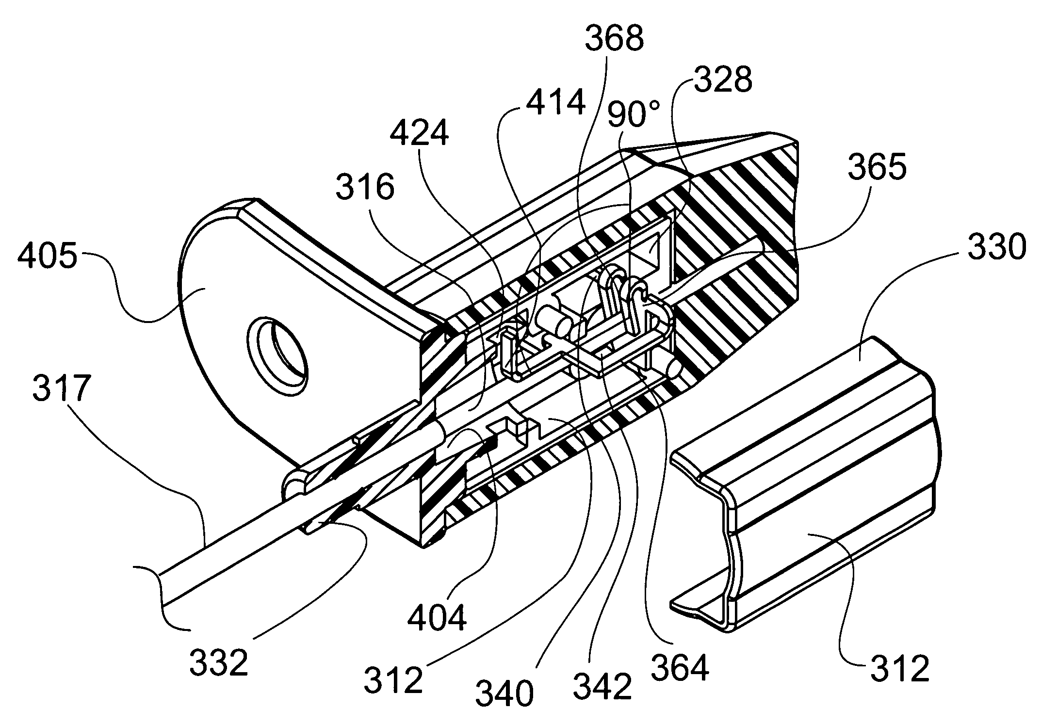
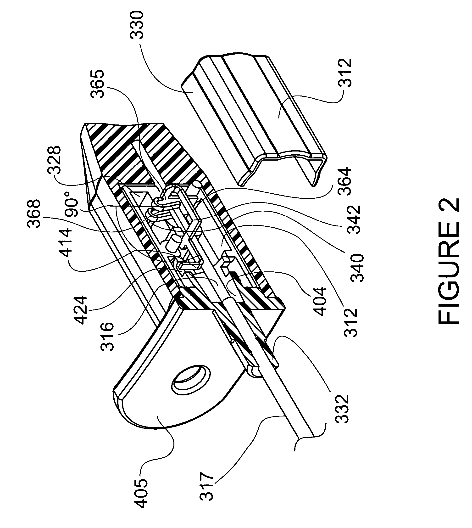
[0014]The binding member includes at least one drag inducing member such that the member engages the inner needle during slidable receipt of the inner needle to create a drag force with the inner needle. The drag force facilitates rotation of the binding member relative to a longitudinal axis of the inner needle such that the binding surfaces engage the inner needle to prevent slidable movement of the inner needle in the extended position of the shield. The binding member further includes a needle communicating surface extending therefrom such that the needle communicating surface is engageable with the inner needle to prevent rotation of the binding member. A retainer extends transversely from the needle communicating surface for releasable engagement with the needle hub.
[0027]The binding member includes at least one drag inducing member which engages the outer needle cannula during slidable receipt of the outer needle cannula to create a drag force with the outer needle cannula. The drag force facilitates rotation of the binding member relative to a longitudinal axis of the outer needle cannula such that the binding surfaces engage the outer needle cannula to prevent slidable movement of the outer needle cannula in the extended position of the shield. The binding member further includes a needle communicating surface extending therefrom such that the needle communicating surface is engageable with the outer needle cannula to prevent rotation of the binding member.
[0033]The shield includes a binding member disposed within the shield which defines binding surfaces. The binding surfaces form an aperture configured for slidable receipt of the inner needle between the retracted position and the extended position. The binding member includes at least one drag inducing member such that the drag inducing member engages the inner needle during slidable receipt of the inner needle to create a drag force with the inner needle. The drag force facilitates rotation of the binding member relative to a longitudinal axis of the inner needle such that the binding surfaces engage the inner needle to prevent slidable movement of the inner needle in the extended position of the shield.
Problems solved by technology
Under such conditions, it is difficult to properly dispose of a used needle while caring for a patient.
Problems of current safety devices include difficulty of use and high cost due to their complexity and number of parts.
Heretofore, known medical needle shield devices do not accommodate adequate viewing of fluid flashback.
These devices, however, may disadvantageously misfire or be cumbersome to activate.
Further drawbacks of current devices include high manufacturing costs due to complexity and the number of parts.
Thus, these types of prior art devices may not adequately and reliably shield medical needle apparatuses to prevent hazardous exposure.
Method used
Image
Click on the blue label to locate the original text in one second.
Reading with bidirectional positioning of images and text.
Examples
Embodiment Construction
[0102]The exemplary embodiments of the medical needle shield apparatus and methods of operation disclosed are discussed in terms of medical needles for infusion of intravenous fluids, medication infusion or fluid collection, guiding of other needles, e.g., biopsy, and more particularly, in terms of needle shield apparatus employed with a needle cannula that prevent hazardous exposure to the needle tip, including, for example, inadvertent needle sticks. It is envisioned that the present disclosure, however, finds application to a wide variety of cannula needles and devices for the infusion of preventive medications, medicaments, therapeutics, etc. to a subject, such as, for example, epidural needles, spinal needles, biopsy needles, chiba needles, potts cournand needles, coaxial introducer needles, Y-sites, etc.
[0103]It is also envisioned that the present disclosure may be employed for collection of body fluids and / or tissues, including those collected during procedures relating to so...
PUM
Abstract
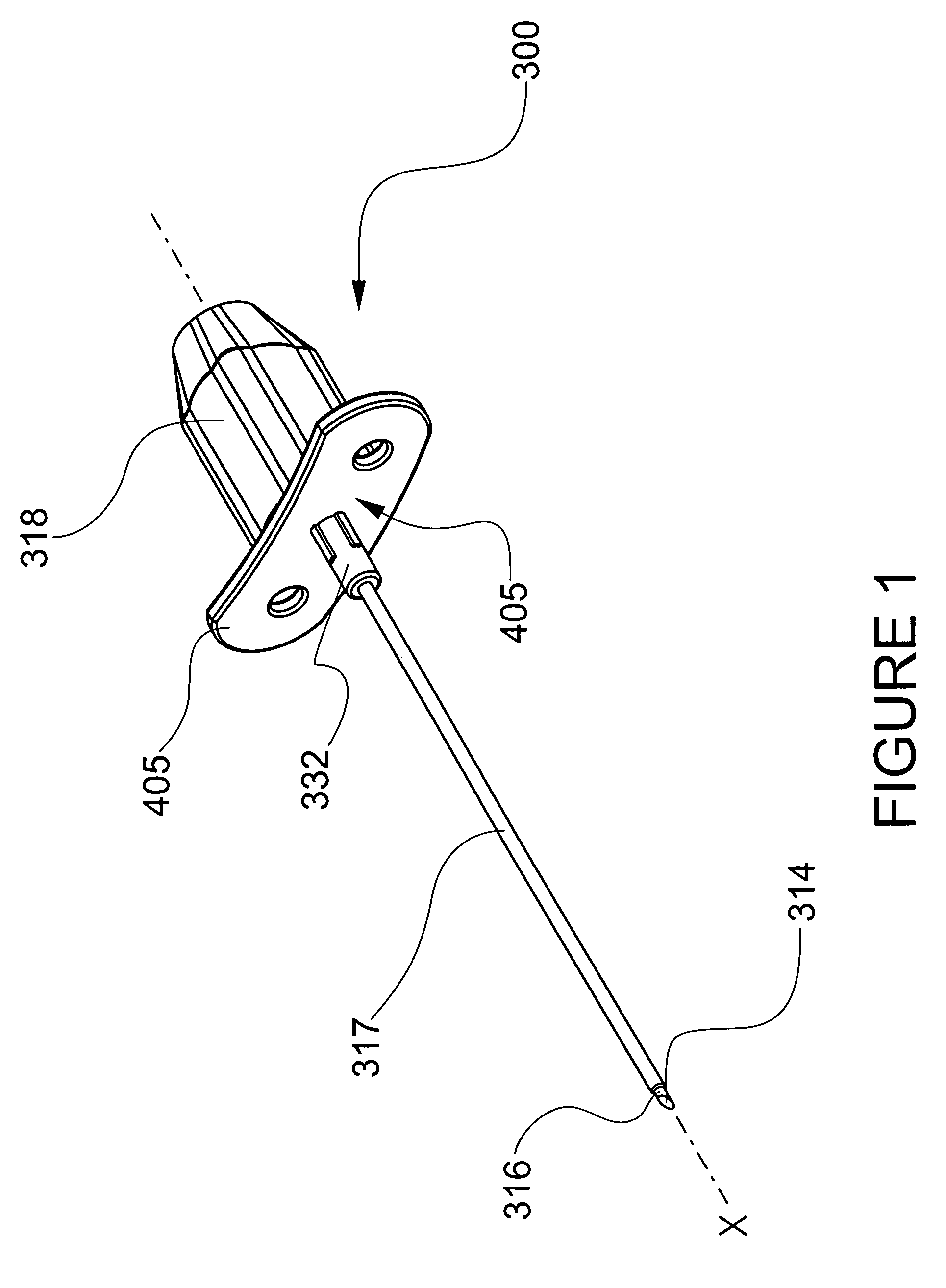
A medical needle shield apparatus is provided that includes a needle hub having a needle cannula extending therefrom. At least one shield is extensible from a retracted position to an extended position to enclose a distal end of the needle. The shield includes a binding member disposed within the shield and defines binding surfaces that form an aperture configured for slidable receipt of the inner needle. The binding member includes at least one drag inducing member that engages the inner needle during slidable receipt to create a drag force. The drag force facilitates rotation of the binding member such that the binding surfaces engage the inner needle to prevent slidable movement. The shield and / or hub includes a retention element engageable between the shield and hub and a sheath retention element. The hub includes a magnifier for viewing fluid flashback.
Description
CROSS-REFERENCE TO RELATED APPLICATIONS[0001]This patent application is a continuation-in-part of U.S. Utility patent application Ser. No. 10 / 409,819, filed in the U.S. Patent and Trademark Office on Apr. 8, 2003 now U.S. Pat. No. 6,796,962 by Ferguson et al., which is a continuation-in-part of U.S. Utility application Ser. No. 10 / 322,288, filed in the U.S. Patent and Trademark Office on Dec. 17, 2002 now U. S. Pat. No. 7,004,927 by Ferguson et al., which claims priority to U.S. Provisional Patent application Serial No. 60 / 424,655, filed in the U.S. Patent and Trademark Office on Nov. 7, 2002 by Bagley et al., and U.S. Utility patent application Ser. No. 10 / 202,201, filed in the U.S. Patent and Trademark Office on Jul. 23, 2002 by Ferguson et al., which is a continuation-in-part of U.S. Utility patent application Ser. No. 09 / 809,357, filed in the U.S. Patent and Trademark Office on Mar. 15, 2001 by Ferguson et al., the entire contents of each of these disclosures being hereby incorp...
Claims
Application Information
Patent Timeline
Application Date:The date an application was filed.
Publication Date:The date a patent or application was officially published.
First Publication Date:The earliest publication date of a patent with the same application number.
Issue Date:Publication date of the patent grant document.
PCT Entry Date:The Entry date of PCT National Phase.
Estimated Expiry Date:The statutory expiry date of a patent right according to the Patent Law, and it is the longest term of protection that the patent right can achieve without the termination of the patent right due to other reasons(Term extension factor has been taken into account ).
Invalid Date:Actual expiry date is based on effective date or publication date of legal transaction data of invalid patent.

