Resettable safety shield for medical needles

a safety shield and needle technology, applied in the field of safety shields for medical needles, can solve the problems of difficulty in properly disposing of used needles, high cost, and difficulty in use, and achieve the effect of effectively and inexpensively protecting the tip of a medical needl

Inactive Publication Date: 2012-01-17
SPECIALIZED HEALTH PRODS
View PDF125 Cites 16 Cited by
  • Summary
  • Abstract
  • Description
  • Claims
  • Application Information

AI Technical Summary

Benefits of technology

[0010]Accordingly, the present disclosure addresses a need for a medical needle shield apparatus which effectively and inexpensively protects a tip of a medical needle after use. The present disclosure resolves related disadvantages and drawbacks experienced in the art. More specifically, the apparatus and method of this invention constitute an important advance in the art of safety needle devices.
[0013]The binding member includes at least one drag inducing member such that the member engages the inner needle during slidable receipt of the inner needle to create a drag force with the inner needle. The drag force facilitates rotation of the binding member relative to a longitudinal axis of the inner needle such that the binding surfaces engage the inner needle to prevent slidable movement of the inner needle in the extended position of the shield. The binding member further includes a needle communicating surface extending therefrom such that the needle communicating surface is engageable with the inner needle to prevent rotation of the binding member. A retainer extends transversely from the binding member for releasable engagement with the needle hub.

Problems solved by technology

Under such conditions, it is difficult to properly dispose of a used needle while caring for a patient.
Problems of current safety devices include difficulty of use and high cost due to their complexity and number of parts.
These devices, however, may disadvantageously misfire or be cumbersome to activate.
Further drawbacks of current devices include high manufacturing cost due to complexity and the number of parts.
Thus, these type prior art devices may not adequately and reliably shield medical needle apparatus to prevent hazardous exposure.

Method used


Image

  • Resettable safety shield for medical needles
  • Resettable safety shield for medical needles
  • Resettable safety shield for medical needles

Examples


Embodiment Construction

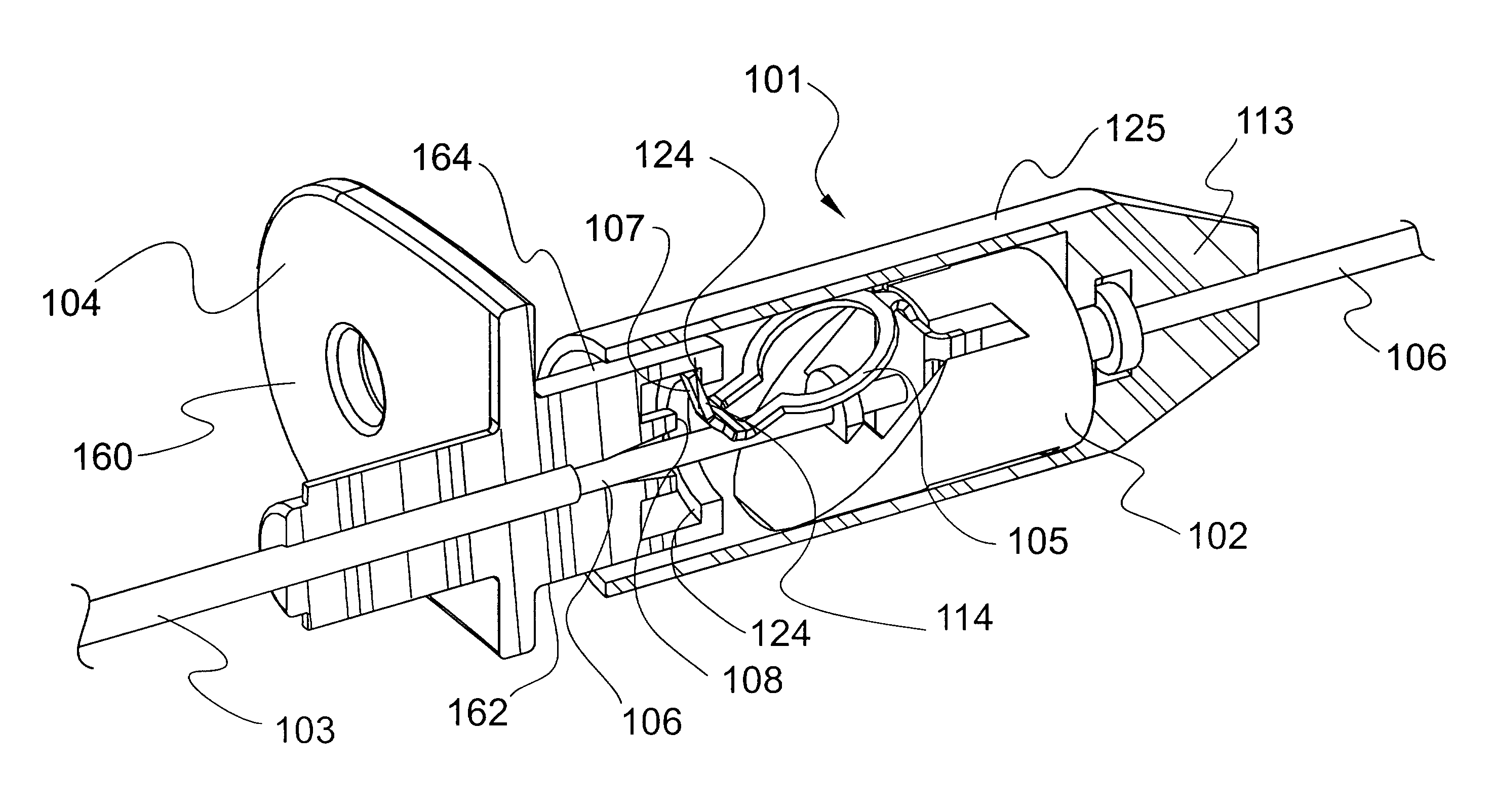
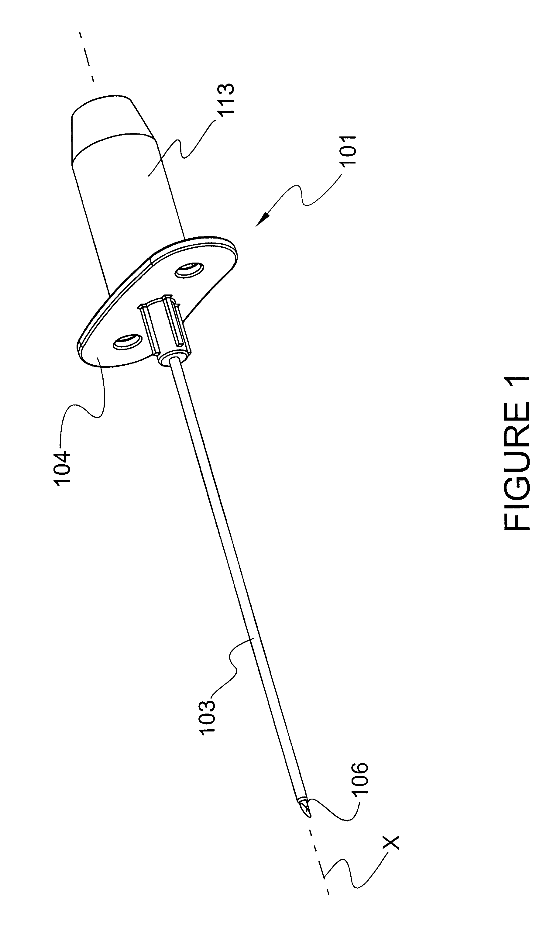
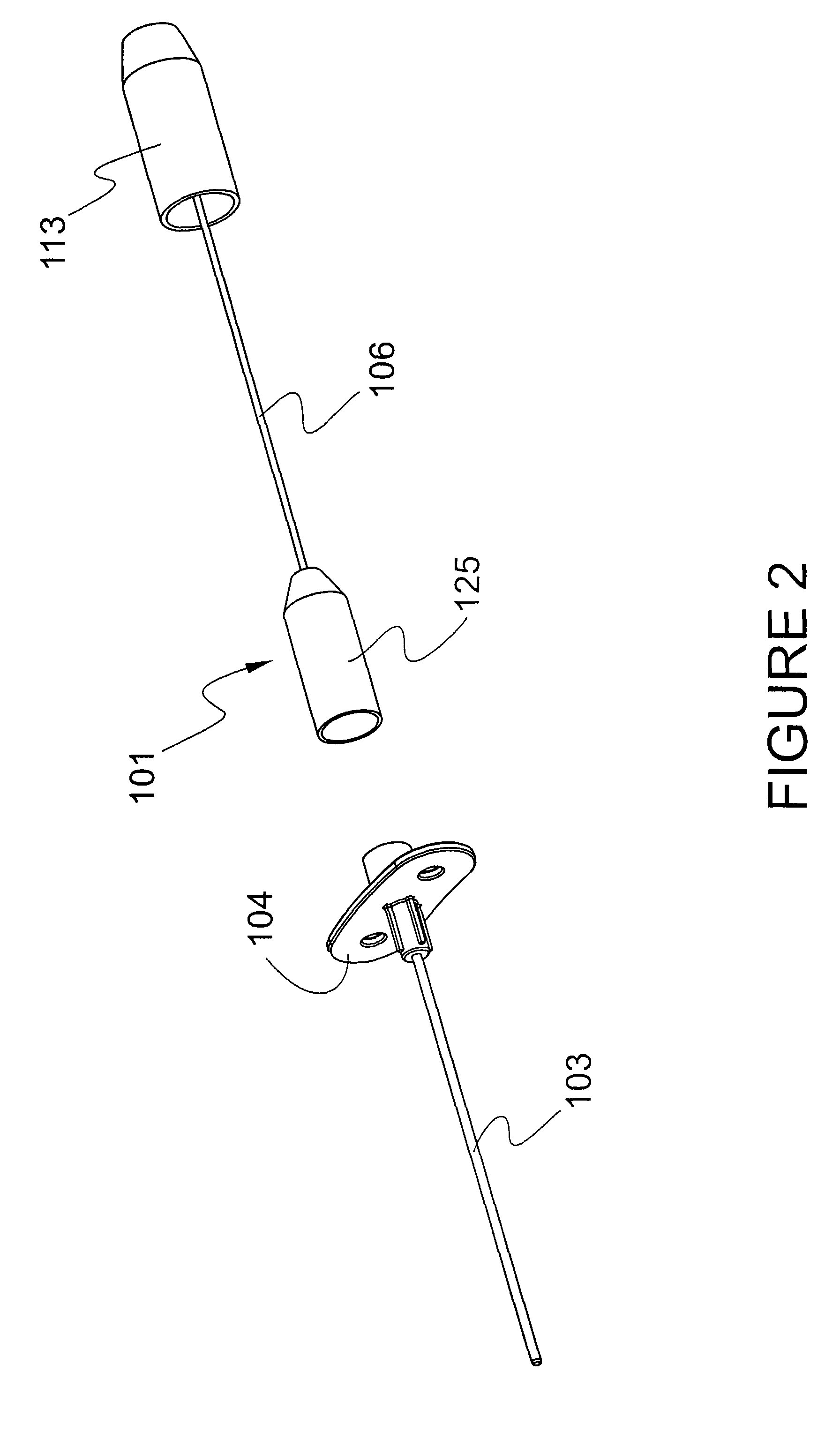
[0114]The exemplary embodiments of the medical needle shield apparatus and methods of operation disclosed are discussed in terms of medical needles for infusion of intravenous fluids, medication infusion or fluid collection, guiding of other needles, e.g., biopsy, and more particularly, in terms of needle shield apparatus employed with a needle cannula that prevent hazardous exposure to the needle tip, including, for example, inadvertent needle sticks. It is envisioned that the present disclosure, however, finds application to a wide variety of cannula needles and devices for the infusion of preventive medications, medicaments, therapeutics, etc. to a subject, such as, for example, epidural needles, spinal needles, biopsy needles, chiba needles, potts cournand needles, coaxial introducer needles, Y-sites, etc. It is also envisioned that the present disclosure may be employed for collection of body fluids and / or tissues, including those employed during procedures relating to soft tis...


PUM


Abstract

A medical needle shield apparatus is provided that includes a needle hub (104) having an outer needle cannula (103) extending therefrom. An inner needle (106) is disposed for slidable movement with the outer needle cannula (103). At least one shield (101) is extensible from a retracted position to an extended position to enclose a distal end of the inner needle (101). The shield (101) includes a binding member (105) disposed within the shield (101) and defines binding surfaces (122) that form an aperture (138) configured for slidable receipt of the inner needle (106). The binding member (105) includes a binding member reset surface (107) aligned with a reset surface (108) for engagement therewith to allow reuse of a shielded needle apparatus.

Description

PRIORITY[0001]This application is a U.S. national stage application under 35 USC §371 of International Application No. PCT / US2004 / 039400, filed Nov. 23, 2004, which claims priority to the following applications: 1) U.S. patent application Ser. No. 10 / 721,526, filed Nov. 25, 2003, now U.S. Pat. No. 7,179,244; 2) U.S. patent application Ser. No. 10 / 739,868, filed Dec. 18, 2003, now U.S. Pat. No. 7,413,562; 3) U.S. Provisional Patent Application No. 60 / 608,565, filed Sep. 10, 2004; and 4) U.S. Provisional Patent Application No. 60 / 622,392, filed Oct. 27, 2004, each of which applications is incorporated by reference in its entirety into this application.BACKGROUND[0002]1. Technical Field[0003]The present disclosure generally relates to safety shields for medical needles, and more particularly, to safety shields that protect a needle point of a medical needle.[0004]2. Description of the Related Art[0005]Problems associated with inadvertent needle sticks are well known in the art of blood...

Claims


Application Information

Patent Timeline
Patent Type & Authority Patents(United States)
IPC IPC(8): A61M5/00A61M5/178A61B19/00A61M5/158A61M5/32A61M5/46A61M25/06
CPCA61M5/3273A61M25/0618A61B2019/4805A61M5/158A61M5/46A61M39/0208A61M2005/1581A61M2005/3247A61M2005/325A61B2090/0801
Inventor SNOW, JEREMY W.FERGUSON, F. MARKSMITH, DANIEL K.BARROS, ROY L.SOLOMON, DONALD D.THORNE, DAVID L.VANDERSTEK, BRADLEY J.
Owner SPECIALIZED HEALTH PRODS
Why Eureka
Try Eureka