Light pen system for pixel-based displays

a technology of pixel-based displays and light pen systems, which is applied in the field of input devices for interaction with display systems, can solve the problems that the light pen technique based on the timing of the raster scan is not applicable to these newer display modalities

Inactive Publication Date: 2008-09-02
MITSUBISHI ELECTRIC RES LAB INC
View PDF11 Cites 37 Cited by
  • Summary
  • Abstract
  • Description
  • Claims
  • Application Information

AI Technical Summary

Benefits of technology

[0010]In the spatial embodiment, the location is encoded by unique intensity variations over a neighboring region of pixels. Therefore, a neighborhood of pixels is sampled in order to determine a pixel location. This embodiment uses multiple photo-sensors. As an advantage over the temporal embodiment, the spatial implementation can determine the location from a single pattern.

Problems solved by technology

Unfortunately, the traditional scanned CRT-based displays are being replaced by pixel-oriented displays, such as LCD screens, digital-mirror arrays, and organic LED technologies.
These pixel-based displays are not scanned, and thus the traditional light pen technique based on the timing of the raster scan is not applicable for these newer display modalities.

Method used


Image

  • Light pen system for pixel-based displays
  • Light pen system for pixel-based displays
  • Light pen system for pixel-based displays

Examples


Embodiment Construction

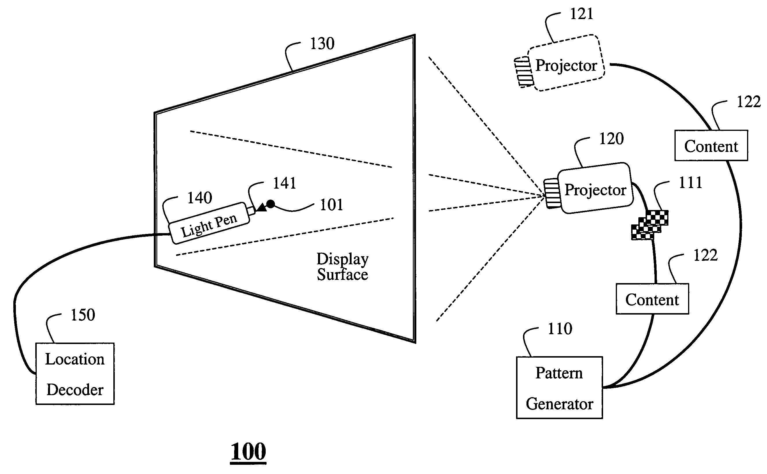
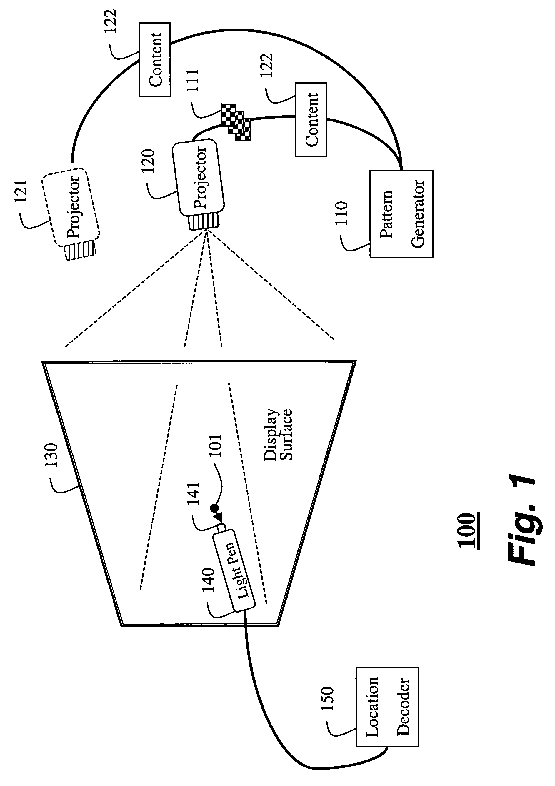
[0022]FIG. 1 shows a light pen system 100 for a pixel-based display. The system includes a pattern and content generator 10 coupled to an image generator 120, e.g., a projector. The image generator renders a sequence of patterns 111 on a display surface 130. In the preferred embodiment, the display surface is pixel-based, instead of raster scanned, although the system also works with raster-scanned displays. The system also includes a light pen 140 coupled to a location decoder 150. The task it to determine 2D coordinates of an arbitrary location 101 on the display surface 130.

[0023]The image generator 120 can use a LCD screen, a digital-mirror array, liquid crystal on silicon (LCOS), and organic LED technologies in either front or rear projection modes. It should be noted that the invention can also be used with conventional CRT-based displays. The light pen can use a single photo-sensor 141 or an array of, e.g., CCD, sensors as in a camera. The light pen can include a pressure sen...


PUM


Abstract

An interactive display system includes a pixel-based display surface and a light pen. A sequence of patterns is projected onto the display surface. The sequence of patterns has a unique sequence of light intensities for each location of the display surface. Intensities of light at an arbitrary location are sensed by the light pen while projecting the sequence of patterns. The intensifies of light are decoded to determine coordinates of the arbitrary location.

Description

FIELD OF THE INVENTION[0001]This invention relates generally to input devices for interaction with display systems, and more particularly to light pens used with such displays.BACKGROUND OF THE INVENTION[0002]Light pens are often used as input devices with graphic user interfaces, see Myers, “A Brief History of Human Computer Interaction Technology,” ACM Interactions, Vol. 5, no. 2, pp. 44-54, March 1998, for a brief history. Although light pens have been used since 1954, it was the work of Ivan Sutherland at Lincoln Laboratories, that popularized the use of light pens with computers, Sutherland, “Sketchpad: The First Interactive Computer Graphics,” Ph.D. Thesis, MIT, 1963.[0003]As an input device, a light pen has some advantages over a mouse. The mouse is an indirect input device. Movement of the mouse on a horizontal surface causes movement of a cursor on a vertical display. The amount of movement, and speed of movement of the mouse and cursor can be different. In contrast, the po...

Claims


Application Information

Patent Timeline
Patent Type & Authority Patents(United States)
IPC IPC(8): G06K9/00G06F3/00G06F3/033G06F3/042G09G5/00
CPCG06F3/03542G06F3/0321
Inventor DIETZ, PAUL H.LEIGH, DARREN L.RASKAR, RAMESHLEE, JOHNNY CHUNG
Owner MITSUBISHI ELECTRIC RES LAB INC
Why Eureka
Try Eureka