Image forming apparatus and video receiving and display apparatus

a technology of image forming apparatus and video receiving and display apparatus, which is applied in the direction of instruments, television systems, signal generators with optical-mechanical scanning, etc., can solve the disadvantages of artificial motion of objects in video, flicker annoyance, and obtrusive flicker annoyance, so as to reduce the artificiality of motion of objects.

Inactive Publication Date: 2008-09-16
CANON KK
View PDF7 Cites 1 Cited by
  • Summary
  • Abstract
  • Description
  • Claims
  • Application Information

AI Technical Summary

Benefits of technology

[0011]It is an object of the present invention to provide an image display apparatus and a video receiving and display apparatus that reduce an artificiality of a motion of an object generated when one image is displayed a plurality of times.

Problems solved by technology

A screen on which video signals are displayed in this cycle often causes a flicker annoyance.
The flicker annoyance is obtrusive particularly in a large-screen image display apparatus.
Similarly to the above, in the video displayed by the 3-2 pulldown-converted video signals, therefore, the display position does not coincide with the expected position on the screen and the motion of the object in the video disadvantageously appears artificial.

Method used


Image

  • Image forming apparatus and video receiving and display apparatus
  • Image forming apparatus and video receiving and display apparatus
  • Image forming apparatus and video receiving and display apparatus

Examples


first embodiment

[0100]In a first embodiment, an input non-interlace video signal corresponding to one frame is divided into video signals corresponding to two fields and the video signals corresponding to the respective fields are displayed by the interlace scan.

[0101]FIG. 4 is a timing chart that depicts a display timing control according to this embodiment.

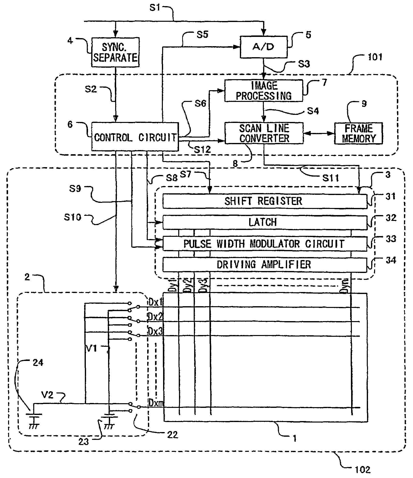
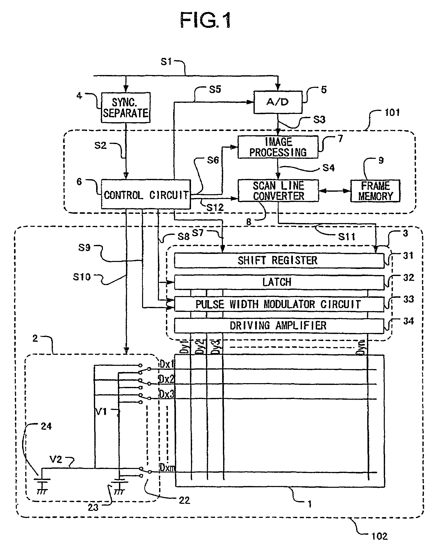
[0102]The scan line converter 8 temporarily stores the display signal S4 of a non-interlace structure in the frame memory 9, sequentially reads data corresponding to each row from the frame memory 9 in order of (1, 3, 5, 7, . . . , 2, 4, 6, 8, . . . ) by a delay by as much as one frame, and outputs the data as the scan line converted signal S11. The scan lines are thereby converted into an interlace structure.

[0103]The scan driver 2 interlace-scans the scan wirings Dx1 to Dxm. More specifically, the scan driver 2 makes every two lines in selected states simultaneously in order of (Dx1, Dx2), (Dx3, Dx4), (Dx5, Dx6), . . . , and scans the scan wi...

second embodiment

[0107]In a second embodiment, an input non-interlace video signal corresponding to one frame is duplicated into video signals corresponding to two sub-frames and the video signals corresponding to the respective sub-frames are displayed by the non-interlace scan.

[0108]FIG. 7 is a timing chart that depicts a display timing control according to this embodiment.

[0109]The scan line converter 8 temporarily stores the display signal S4 in the frame memory 9, sequentially reads data corresponding to each row from the frame memory 9 in order of (1, 2, 3, 4, 5, . . . , 1, 2, 3, 4, 5, . . . ) by a delay by as much as one frame, and outputs the data as the scan line converted signal S11. At this time, the scan line converter 8 executes reading and output at a rate twice as fast as that for the display signal S4.

[0110]The scan driver 2 scans the scan wirings Dx1 to Dxm by one row by one row. More specifically, the scan driver 2 first scans the scan wirings while making the scan wirings in selec...

third embodiment

[0114]In the first embodiment, every two scan wirings are set into selected states during the interlace scan. In a third embodiment, every one scan wiring is set into a selected state. The other configurations are the same as those according to the first embodiment.

[0115]FIG. 8 is a timing chart that depicts a display timing control according to this embodiment.

[0116]The scan line converter 8 temporarily stores the display signal S4 of the non-interlace structure in the frame memory 9, sequentially reads data corresponding to each row from the frame memory 9 in order of (1, 3, 5, 7, 2, 4, 6, 8, . . . ) by a delay by as much as one frame, and outputs the data as the scan line converted signal S11. The scan lines are thereby converted into an interlace structure.

[0117]The scan driver 2 makes every one line in selected states in order of Dx1, Dx3, Dx5, . . . , and scans the scan wirings so as to shift the scan wiring by as many as two lines. The scan driver 2 then scans the scan wiring...


PUM


Abstract

A control circuit of an image display apparatus controls an output of video signals so that a non-display period TC set between an end of display of images corresponding to a first input video signal for one vertical scan and a start of display of an image corresponding to a second input video signal for the next one vertical scan can satisfy a relationship:TC>(TA−TB) / N,where TA denotes a period between the start of the display of the images corresponding to the first input video signal and the start of the display of the image corresponding to the second input video signal,TB denotes a sum of display periods for the respective images corresponding to the first input video signal, andN denotes the number of the images corresponding to the first input video signal.

Description

BACKGROUND OF THE INVENTION[0001]1. Field of the Invention[0002]The present invention relates to an image forming apparatus and a video receiving and display apparatus for displaying a plurality of images based on a video signal corresponding one image.[0003]2. Description of the Related Art[0004]A technique for displaying an image twice by performing two vertical scans on the image based on an input video signal corresponding to one frame so as to reduce flicker or a so-called double-speed display technique is disclosed in Japanese Patent Laid-Open No. 2004-219884.[0005]An image display technique for emitting a light from a device so that a luminance time width in sub-fields is half a time width of the sub-fields (50% duty ratio) is disclosed in Japanese Patent Application Laid-Open No. H09-083911 (corresponding U.S. Pat. Nos. 6,100,939 and 6,333,766).[0006]An image display technique for putting at least one non-display field between two frames and for approximating a display schem...

Claims


Application Information

Patent Timeline
Patent Type & Authority Patents(United States)
IPC IPC(8): H04N3/14
CPCG09G3/20G09G3/22G09G3/2014G09G3/2022G09G2310/021G09G2340/0435G09G2310/065G09G2320/0247G09G2320/0261G09G2320/10G09G2310/0229
Inventor ANDO, MUNEKI
Owner CANON KK
Why Eureka
Try Eureka