Head mounted display, information processing apparatus, image display apparatus, image display system, method for sharing display of head mounted display, and computer program
a head mounted display and display technology, applied in the field of head mounted displays, can solve the problems of unnatural reflection to the operation is unlikely to be artificially reflected in the eyes of the third person, so as to reduce the artificiality of the operation
- Summary
- Abstract
- Description
- Claims
- Application Information
AI Technical Summary
Benefits of technology
Problems solved by technology
Method used
Image
Examples
first embodiment
A. First Embodiment
A-1. Configuration of Image Display System
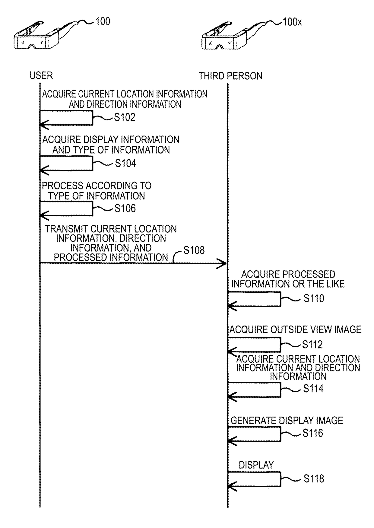
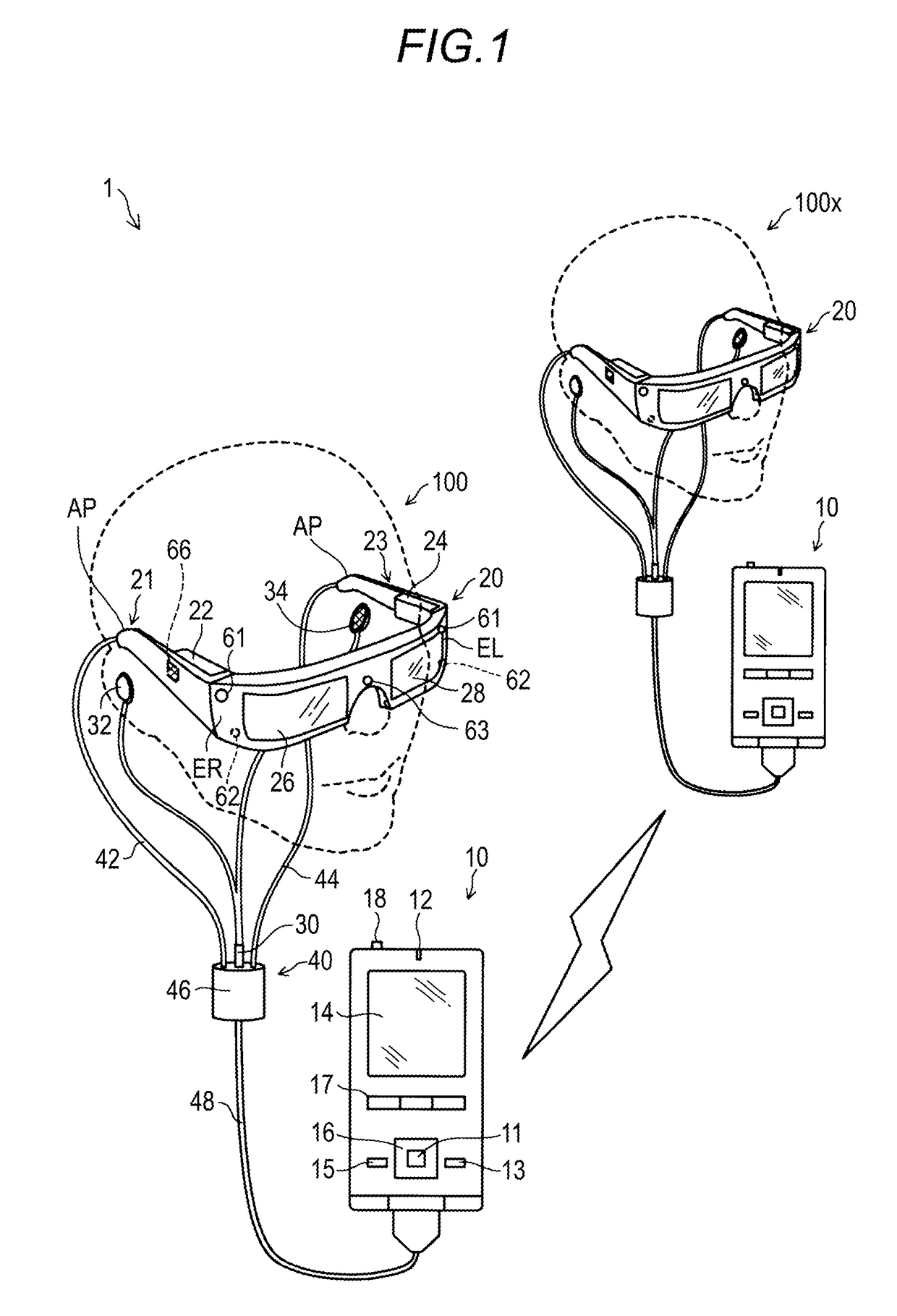
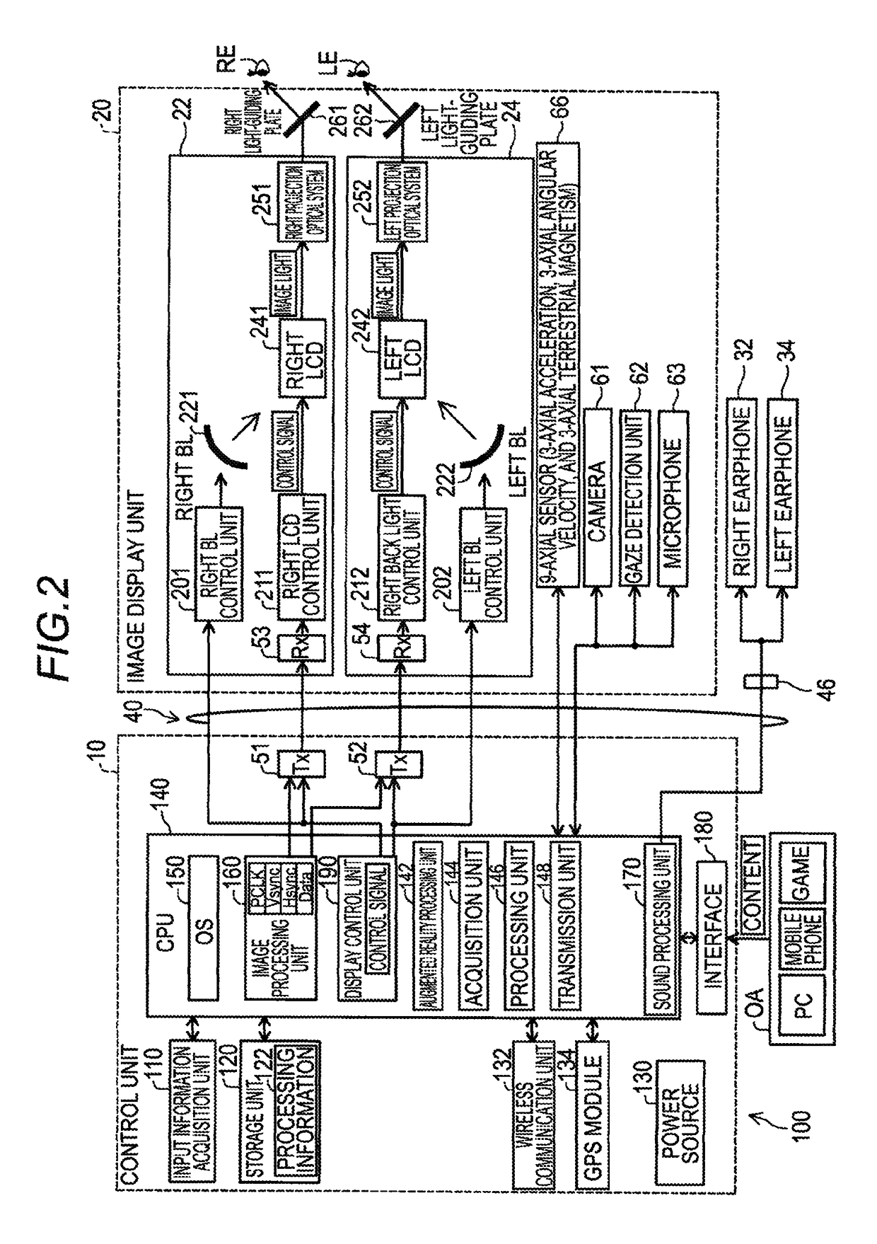
[0076]FIG. 1 is an explanatory diagram illustrating the schematic configuration of an image display system according to an embodiment of the invention. An image display system 1 includes a head mounted display 100 and a head mounted display 100x. Both the head mounted displays 100 and 100x are display apparatuses mounted on the head, and are called a Head Mounted Display (HMD). Both the HMDs 100 and 100x are optical transmission-type head mounted displays which enable users to visually recognize a virtual image and at the same time visually recognize an outside view directly. The HMDs 100 and 100x are connected to each other by wireless communication through an access point apparatus which is not shown in the drawing.
[0077]In the embodiment, when a sharing process which will be described later is performed, it is possible to cause the user of the HMD 100x to visually recognize information (hereinafter, referred to as “disp...
second embodiment
B. Second Embodiment
B-1. Configuration of Image Display System
[0158]In a second embodiment of the invention, a configuration, in which display information is shared between the head mounted display and the image display apparatus that are located in different locations (places), will be described. Hereinafter, only parts, in which configurations and operations are different from those of the third variation according to the first embodiment (FIGS. 7 to 9), will be described. Meanwhile, reference symbols, which are the same as in the third variation which is described above, are attached to the configurations and operations which are the same as in the third variation according to the first embodiment, and the detailed descriptions thereof are not repeated. That is, configurations and operations which will not be described below are the same as the above-described third variation.
[0159]FIG. 10 is an explanatory diagram illustrating the schematic configuration of an image display syst...
third embodiment
C. Third Embodiment
C-1. Configuration of Image Display System
[0181]In a third embodiment of the invention, a configuration in which information, the display situation of which is different, is shared between the image display apparatuses will be described. Hereinafter, only parts, in which configurations and operations are different from those of the third variation according to the first embodiment (FIGS. 7 to 9), will be described. Meanwhile, in the drawing, reference symbols, which are the same as in the third variation which is described above, are attached to the configurations and operations which are the same as in the third variation according to the first embodiment, and the detailed descriptions thereof are not repeated. That is, configurations and operations which will be described below are the same as the above-described third variation.
[0182]The image display system according to the third embodiment includes an HMD 100x, a server 300b, and a communication carrier. Mean...
PUM
 Abstract
Description
Claims
Application Information
 - R&D
- Intellectual Property
- Life Sciences
- Materials
- Tech Scout
- Unparalleled Data Quality
- Higher Quality Content
- 60% Fewer Hallucinations
Browse by: Latest US Patents, China's latest patents, Technical Efficacy Thesaurus, Application Domain, Technology Topic, Popular Technical Reports.
© 2025 PatSnap. All rights reserved.Legal|Privacy policy|Modern Slavery Act Transparency Statement|Sitemap|About US| Contact US: help@patsnap.com


