Metal cord

a technology of metal cords and metal wires, applied in the field of metal cords, can solve the problems of bending of metal cords, weakening of all adjacent metal cords, and breaking of all adjacent metal cords, and achieve the effect of overcoming or reducing the problems of mechanical properties and price increases

Inactive Publication Date: 2008-09-23
BEKAERT ADVANCED CORDS AALTER NV
View PDF9 Cites 5 Cited by
  • Summary
  • Abstract
  • Description
  • Claims
  • Application Information

AI Technical Summary

Benefits of technology

[0006]The present invention provides a metal cord, which overcomes or reduces the problems of price increase and decrease of mechanical properties of the metal cord and possibly the object in which the cord is used.
[0022]Such welds have the advantage that they further can be used in the process of cord construction operations, either double or single twisting operations.
[0033]Since the metal cords as subject of the invention, overcomes the presently known technical drawbacks, the cord manufacturer is also able to reduce the waste-level, and the cords can be provided in a more economical way.
[0034]Therefor metal cord as subject of the invention may e.g. be used to reinforce polymer, such as polyurethane, or rubber belts, such as timing belts, elevator or hoisting belts, conveyor belts, V-belts either without ribs or with ribs in longitudinal or perpendicular direction, or can be used for hoisting cables, control cables or in several automotive applications such as tires or window elevator cable. Due to the improved force at rupture of the metal cord as subject of the invention, the risk on a cascade effect can be decreased over a larger load range, as compared to cords being welded over the whole cross-section.

Problems solved by technology

This is since metal cord welds create an inflexible zone in the metal cord, disturbing e.g. the bending of the metal cord.
Further, the weld in the metal cord creates a weak zone as far as mechanical properties such as tensile strength are concerned.
When one metal cord breaks during load, this seems to create a “shock-effect” or “cascade effect”, which usually causes break of all adjacent metal cords, or even the whole belt.
An other disadvantage of the inflexible zone of the weld, using metal cords in polymer or rubber matrices, is that at the welding zone, due to the inflexibility of the weld, the weld tends to migrate in the polymer or rubber in a transversal direction when the metal cord is bend.
This may cause shearing of the matrix.
This specified length causes a significant price increase of the metal cords.
The metal cord manufacturer faces a waste increase, since insufficient lengths of metal cords or intermediate products cannot be sold or used.

Method used


Image

  • Metal cord
  • Metal cord
  • Metal cord

Examples


Embodiment Construction

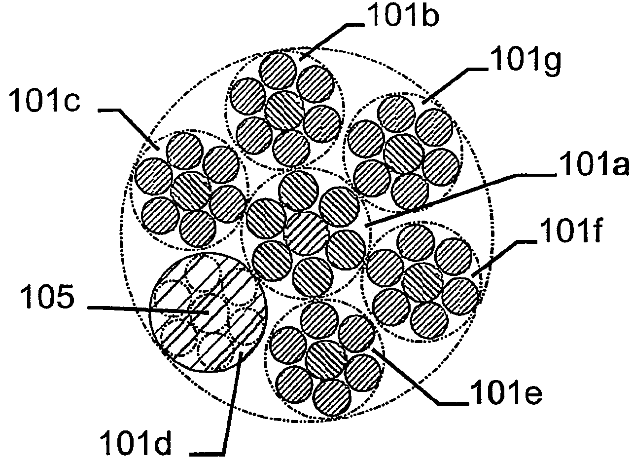
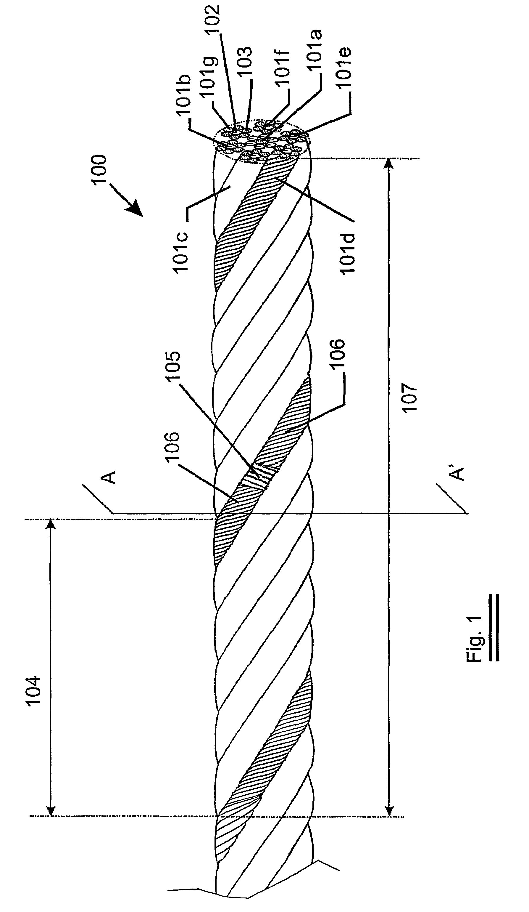
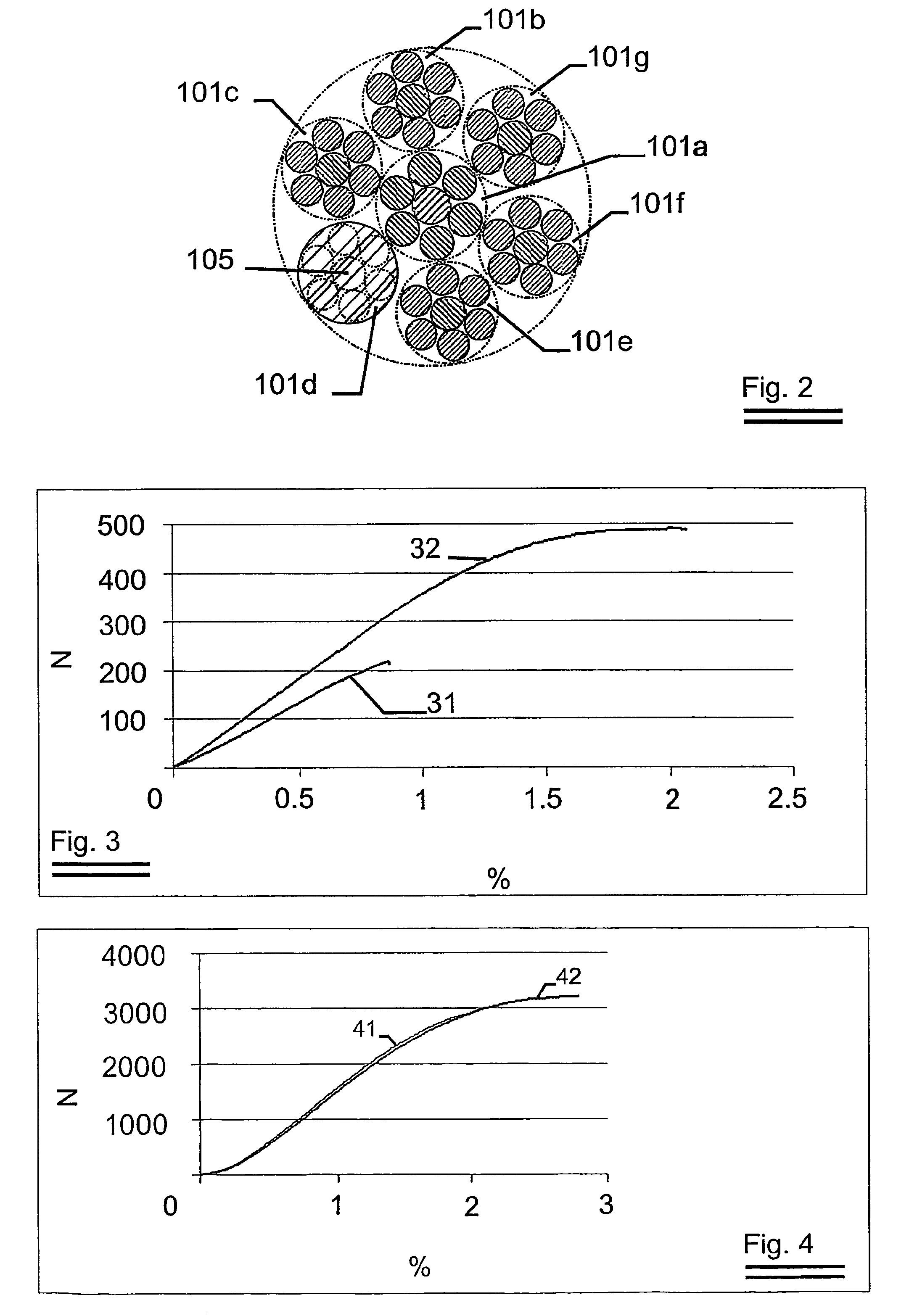
[0041]An embodiment of a metal cord as subject of the invention is shown in FIG. 1. A metal cord 100, provided out of steel having 0.7% C, having a construction “(0.21+6×0.19)+6×(0.19+6×0.175)”. The cord comprises 7 strands (101a, 101b, 101c, 101d, 101e, 101f and 101g). The core strand 101a comprising a core filament 102 of diameter 0.21 mm, being encircled by 6 filaments 103 of a diameter 0.19 mm. The other outer strands 101b, 101c, 101d, 101e, 101f and 101g having all a core filament 102 of diameter 0.19 mm, and 6 encircling filaments 103 of 0.175 mm.

[0042]The lay length 104 of the metal cord 101 is 12.5 mm. The core strand 101a has a lay length of 6.3 mm and the outer strands 101b, 101c, 101d, 101e, 101f and 101g having all a lay length of 8 mm. The core strand 101a and the metal cord itself are twisted in the same direction (S or Z direction) whereas the strands 101b, 101c, 101d, 101e, 101f and 101g all being twined in the opposite direction (Z, respectively S).

[0043]As shown in...


PUM

PropertyMeasurementUnit
elongationaaaaaaaaaa
diameteraaaaaaaaaa
diameteraaaaaaaaaa

Abstract

A metal cord comprising at least two metal strands. At least one strand is welded, with the welded strand having an elongation at rupture of more than 30% of the elongation at rupture of an identical strand without a weld.

Description

[0001]The present invention relates to metal cords and more in particular to the improvement of the tensile strength of the metal cord at welds present over the length of the metal cord.BACKGROUND OF THE INVENTION[0002]At present, using welds to connect two ends of metal cords is avoided as much as possible. This is since metal cord welds create an inflexible zone in the metal cord, disturbing e.g. the bending of the metal cord. Further, the weld in the metal cord creates a weak zone as far as mechanical properties such as tensile strength are concerned. The force at rupture of a welding zone of a cord is usually less than 60% of the force at rupture of the metal cord without the welding zone.[0003]Another important aspect is noticed when several metal cords are used e.g. to reinforce a timing belt or for use in elevator belts. When one metal cord breaks during load, this seems to create a “shock-effect” or “cascade effect”, which usually causes break of all adjacent metal cords, or...

Claims


Application Information

Patent Timeline
Patent Type & Authority Patents(United States)
IPC IPC(8): D02G3/02B23K11/00B23K11/02B23K13/01B65H69/08B66B7/06D07B1/06F16G1/08F16G1/28
CPCB23K11/002B23K11/02B23K13/01B65H69/08D07B7/167B23K11/0073D07B2501/403D07B1/0613D07B1/068D07B2201/1016D07B2401/2005D07B2501/2007D07B2501/2046D07B2501/2076D07B2501/2084
Inventor VANCOMPERNOLLE, STIJNVANDERBEKEN, BERT
Owner BEKAERT ADVANCED CORDS AALTER NV
Why Eureka
Try Eureka