Apparatus and method for mounting photovoltaic power generating systems on buildings

a photovoltaic power generation and building technology, applied in the direction of roof tools, solar thermal energy generation, solar heating energy, etc., can solve the problems that the non-solar cell components required for installing a functioning photovoltaic system become more critical with respect to overall system costs, and achieve the integrity and waterproof characteristics of the supporting roof structure, reduce or substantially eliminate wind uplift forces, and improve the effect of energy production

Inactive Publication Date: 2008-10-14
THE UNITED STATES AS REPRESENTED BY THE DEPARTMENT OF ENERGY
View PDF29 Cites 268 Cited by
  • Summary
  • Abstract
  • Description
  • Claims
  • Application Information

AI Technical Summary

Benefits of technology

[0008]A more specific object is to provide an improved system for mounting PV modules to flat roofs typical of commercial buildings that is economical, requires no special tools for installation and can be used with a variety of roofing surfaces.
[0009]Another specific object of the invention is to provide a system for mounting solar modules on a building roof that eliminates the need for mechanically or adhesively attaching the module-mounting structure to the building roof, whereby to preserve the integrity and waterproof characteristics of the supporting roof structure.
[0010]A further object of the invention is to provide a new and improved system for mounting solar modules on roofs that provides for walkways between rows of solar modules for easy access for servicing and repair.
[0011]Still another object is to provide a photovoltaic module mounting system that is adapted to mount PV modules at a selected tilt angle, e.g., in the range of 0°-15°, to benefit annual energy production.
[0012]A further object is to provide improved means for mounting a plurality of PV modules on a roof that allows the PV modules to shift from a tilt position to a near horizontal position in response to pressure differentials caused by extreme winds, whereby to release wind pressure and reduce or substantially eliminate wind uplift forces.
[0013]These and other objects are achieved by providing a mounting system for PV modules and PV module assemblies in the form of a plurality of mounting stands that are intended to rest on a supporting roof, with each mounting stand consisting of a base plate, and first and second brackets attached to the base plate. The base plate rests on the supporting roof and is sized to introduce a defined separation distance between rows of PV modules to minimize row-to-row shading. The base plate also is sized also to distribute the dead load and to reduce the downward pressure on the supporting roof structure. The first and second brackets are secured at opposite ends of the base plate. These mounting stands are distributed in spaced relation to one another on a supporting roof in a row and column arrangement. The first and second brackets may be of fixed height, with one bracket being taller than the other. Preferably, however, one bracket has a fixed height and the second bracket is constructed to permit its effective height to vary from a first minimum value that is less than that of the first bracket to a second maximum value that is substantially the same as that of the first bracket. In the preferred embodiment, each bracket has dual members for supporting two different PV modules or PV module assemblies. The PV modules are rectangular or square and are supported by the mounting stands by attaching a corner of each module to a different mounting bracket. More specifically, two corners of each module are mounted to different first brackets and the other two corners of each module are attached to different second brackets. The first and second brackets of each mounting stand introduce a controlled gap between adjacent PV modules in a row. The distributed mounting stands and the supported PV modules provide sufficient weight to resist movement by wind uplift forces resulting from wind velocities of up to about 70 miles per hour. Under higher velocity winds, e.g., winds up to about 110 miles per hour, the ability of the mounting stands and the supported PV modules to withstand movement is enhanced and preserved by the ability of the second brackets to extend their heights so as to shift the modules to a near horizontal position, thereby releasing wind pressure on the modules and reducing wind uplift forces. Depending on the size of the modules, several modules may be ganged together to form a discrete PV module assembly, with each PV module assembly being supported at two spaced apart points by separate first brackets and at two other points by separate second brackets.

Problems solved by technology

More precisely, as the cost of solar cells per se has declined, the non-solar cell components required for installing a functioning photovoltaic system become more critical with respect to overall system costs.

Method used


Image

  • Apparatus and method for mounting photovoltaic power generating systems on buildings
  • Apparatus and method for mounting photovoltaic power generating systems on buildings
  • Apparatus and method for mounting photovoltaic power generating systems on buildings

Examples


Embodiment Construction

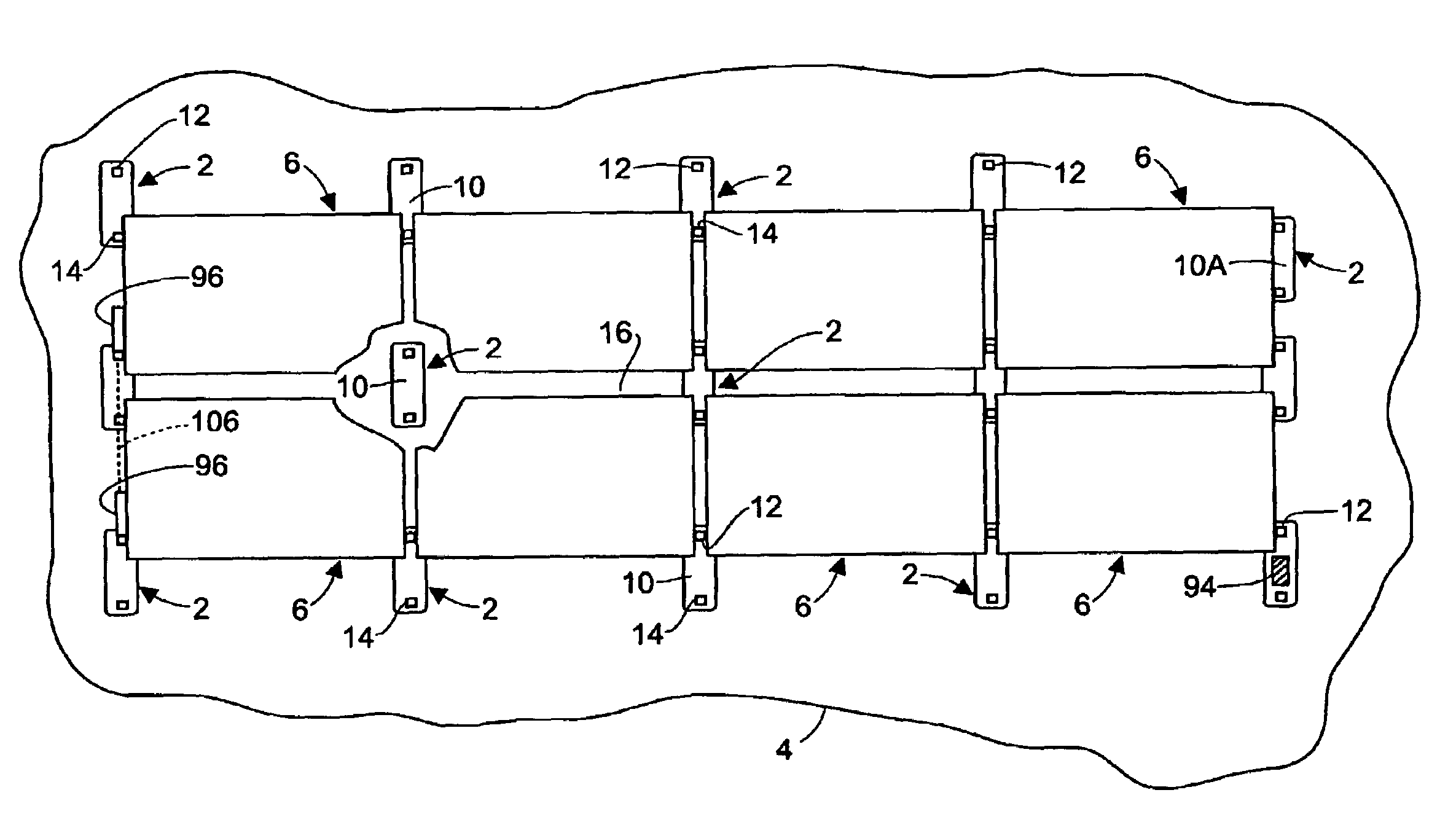
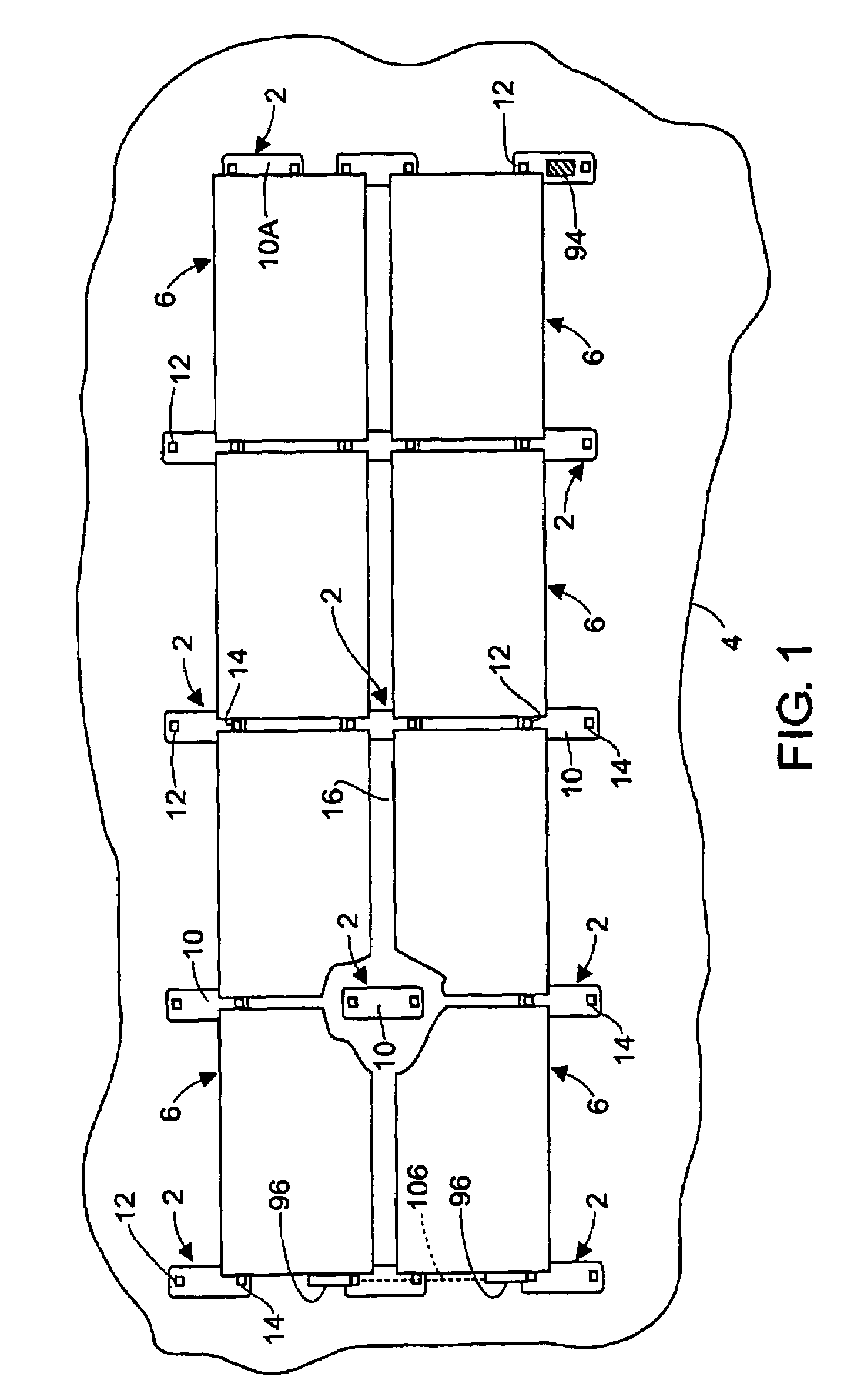
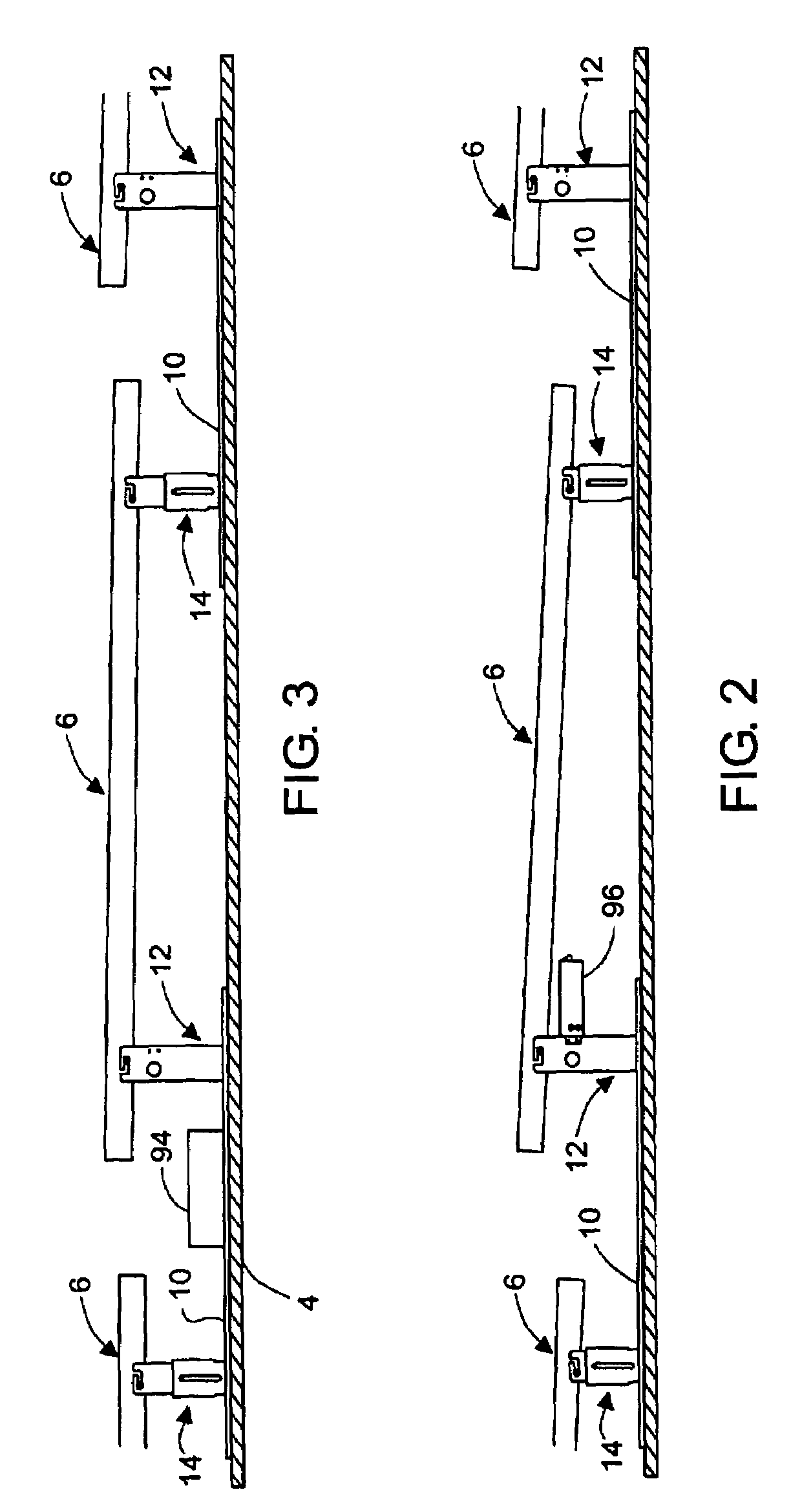
[0030]Referring to FIGS. 1, 2 and 3, the invention comprises a set of mounting stands 2 that are distributed on a supporting roof structure 4 and support a plurality of PV modules 6, with each stand consisting of a base plate 10 and two mutually spaced brackets 12 and 14 that are attached to opposite ends of the base plate. The brackets 12 are of fixed height. The other brackets 14 also may be of fixed height and shorter than brackets 12 in order to provide a selected angle of tilt to PV modules. Preferably, however, the brackets 14 are adjustable in height, as hereinafter described.

[0031]The mounting stands are laid out on a flat roof in a rectangular grid pattern of rows and columns as shown in FIG. 1, with the row and column spacing being determined by the dimensions of the solar modules panels to be mounted as well as the tilt angle and site latitude. Preferably the base plates 10 of the mounting stands are sized to introduce a defined separation distance between the rows of PV ...


PUM


Abstract

Rectangular PV modules (6) are mounted on a building roof (4) by mounting stands that are distributed in rows and columns. Each stand comprises a base plate (10) that rests on the building roof (4) and first and second brackets (12, 14) of different height attached to opposite ends of the base plate (10). Each bracket (12, 14) has dual members for supporting two different PV modules (6), and each PV module (6) has a mounting pin (84) adjacent to each of its four corners. Each module (6) is supported by attachment of two of its mounting pins (84) to different first brackets (12), whereby the modules (6) and their supporting stands are able to resist uplift forces resulting from high velocity winds without the base plates (10) being physically attached to the supporting roof structure (4). Preferably the second brackets (14) have a telescoping construction that permits their effective height to vary from less than to substantially the same as that of the first brackets (12).

Description

[0001]This application claims the benefit of the filing date of U.S. Provisional Application Ser. No. 60 / 371,576, filed 11 Apr. 2002 by Miles C. Russell for “Corner-Jack Photovoltaic Mounting System”.[0002]This invention was made using government funds under Department of Energy Subcontract No. NREL NDO-2-30628-05.FIELD OF THE INVENTION[0003]This invention relates generally to installation of photovoltaic power generating systems and in particular to a novel approach for mounting photovoltaic modules on the roofs of buildings.BACKGROUND OF THE INVENTION[0004]As used herein the term “PV module” identifies a photovoltaic power generating unit in the form of an integrated structure comprising a plurality of electrically interconnected photovoltaic cells and means for supporting and protecting the cells, and the term “PV module assembly” identifies a structure comprising two or more PV modules that are mechanically ganged together and electrically interconnected to form a unitary power ...

Claims


Application Information

Patent Timeline
Patent Type & Authority Patents(United States)
IPC IPC(8): E04D13/18E04C2/52E04D3/36F24J2/52H01L31/042H01L31/048
CPCE04D3/3608H02S20/00F24J2/5211F24J2/5239F24J2/525F24J2/5254F24J2/5264H02S20/23F24J2002/4669F24J2002/5292Y02B10/12Y02B10/20Y02E10/47Y02E10/50Y10S136/291F24J2/4638F24S25/16F24S25/20F24S25/617F24S25/632F24S25/70F24S40/85F24S2025/02F24S2025/6006Y02B10/10
Inventor RUSSELL, MILES CLAYTON
Owner THE UNITED STATES AS REPRESENTED BY THE DEPARTMENT OF ENERGY
Why Eureka
Try Eureka