Reel device for winding an electrical cable thereon

a technology of electrical cables and reels, which is applied in the direction of electrical cable installations, telephone set constructions, and cable arrangements between relatively moving parts, etc., and can solve the problems of inconvenient conduct, relative bulkiness, and replacement of electrical cables

Inactive Publication Date: 2008-10-21
CHEN CHI WEN
View PDF15 Cites 42 Cited by
  • Summary
  • Abstract
  • Description
  • Claims
  • Application Information

AI Technical Summary

Problems solved by technology

The aforementioned conventional reel device is disadvantageous in that it is relatively bulky.
Furthermore, replacement of the electrical cable, when damaged, is inconvenient to conduct.

Method used


Image

  • Reel device for winding an electrical cable thereon
  • Reel device for winding an electrical cable thereon
  • Reel device for winding an electrical cable thereon

Examples


Embodiment Construction

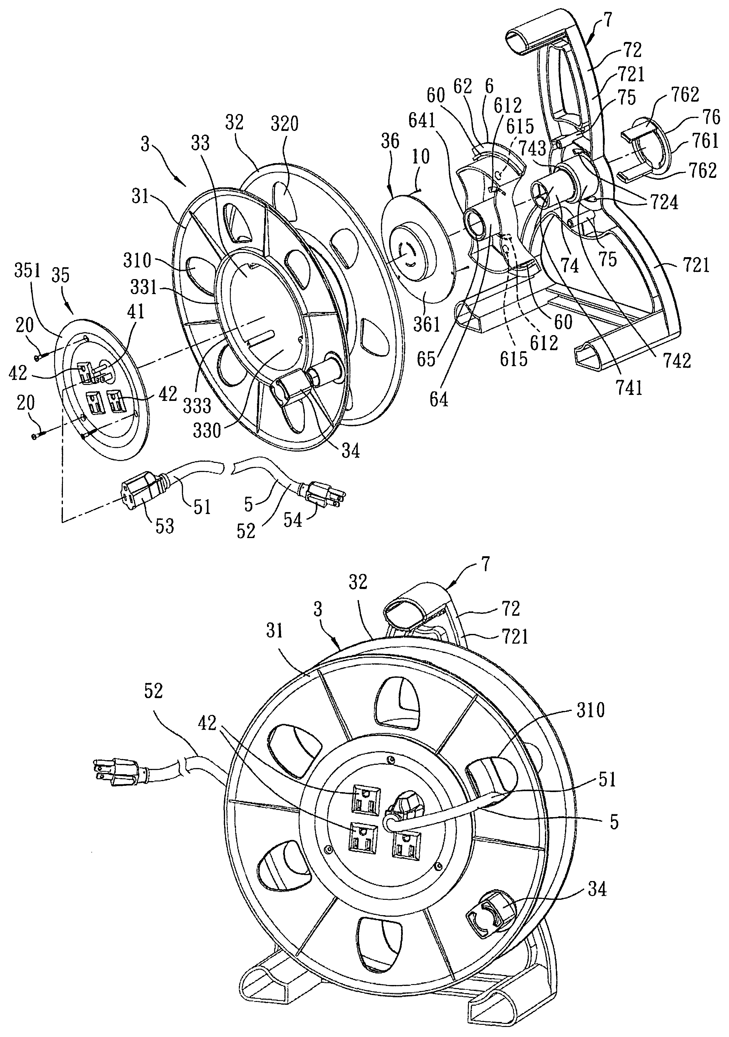
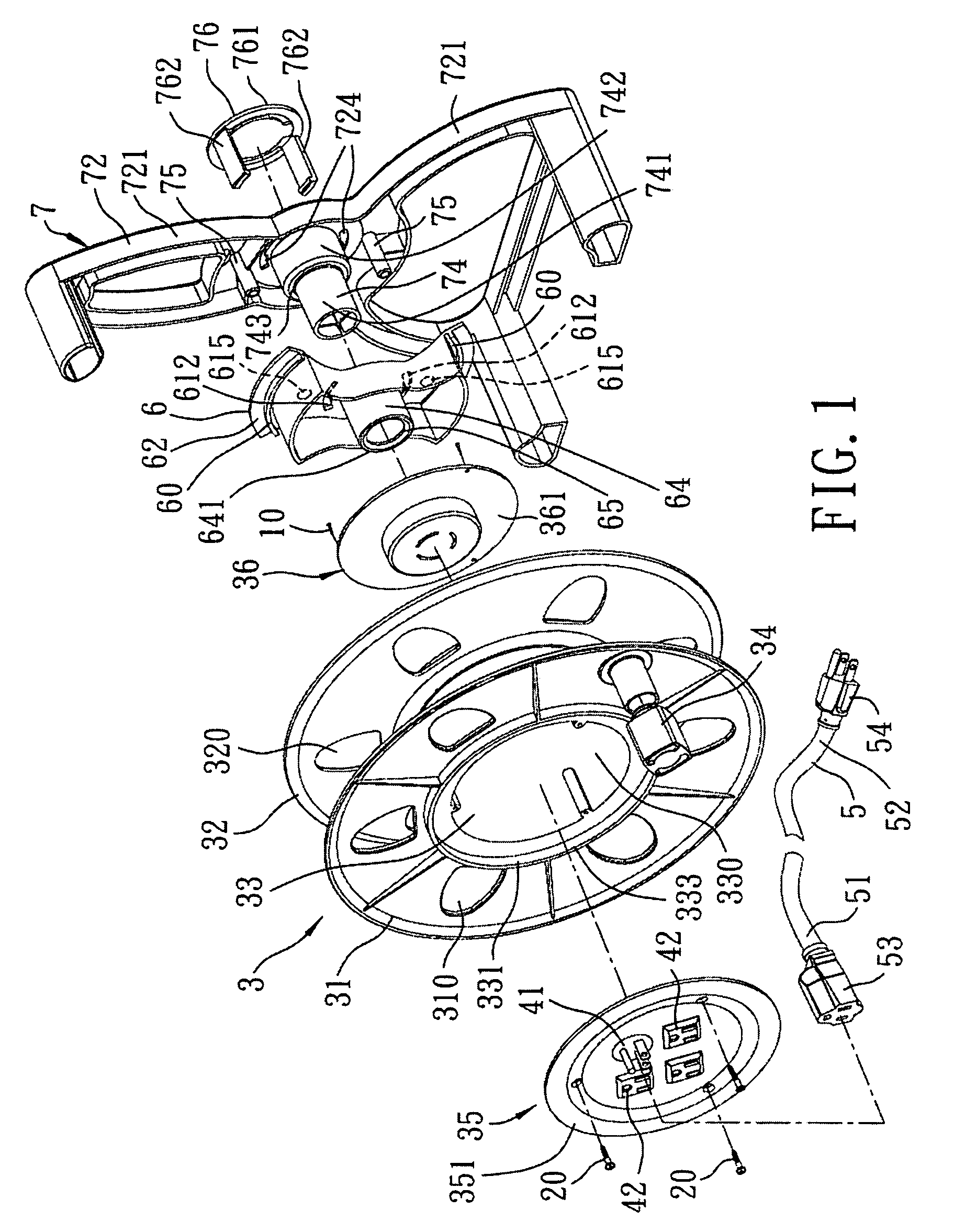
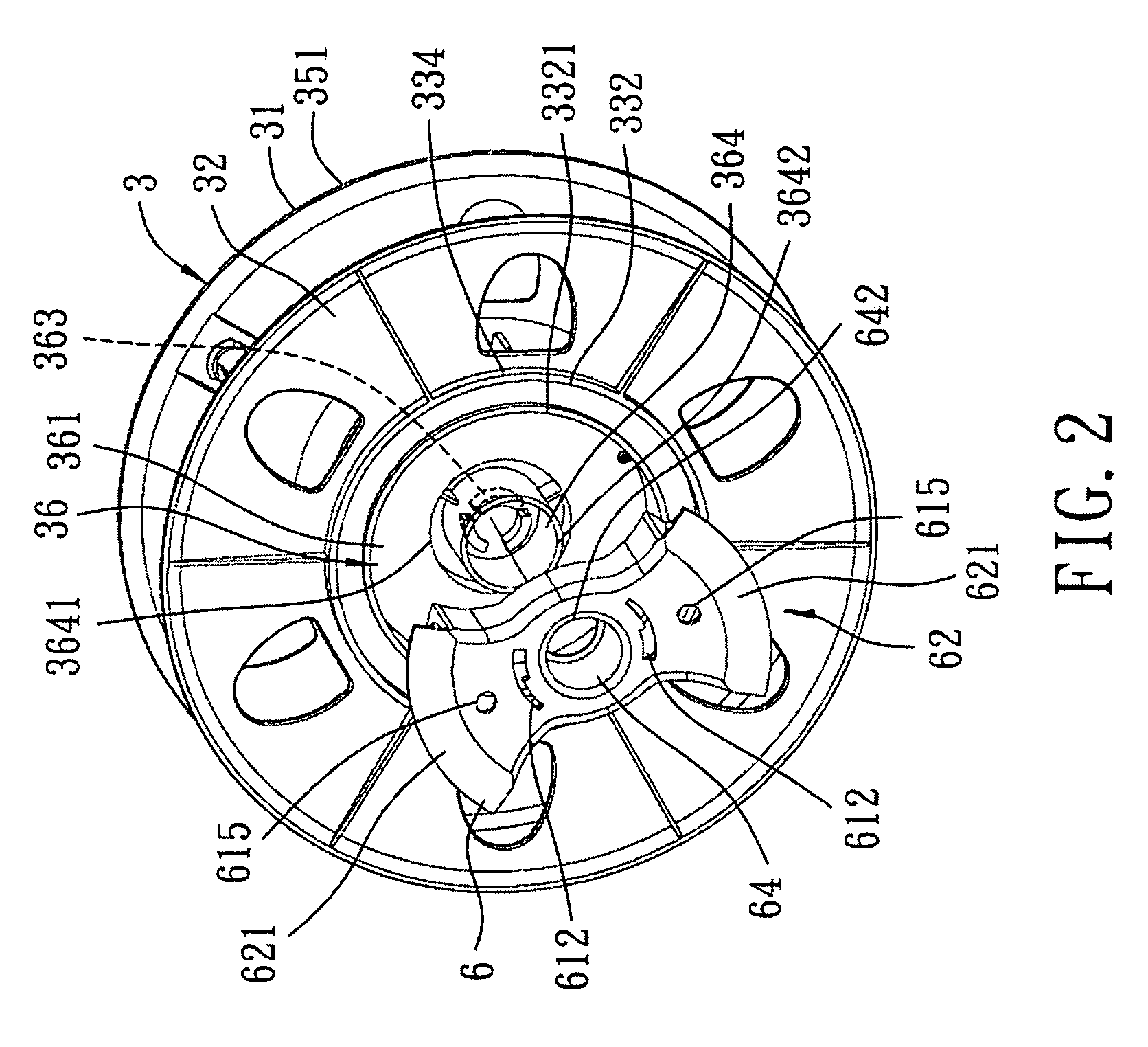
[0014]Referring to FIGS. 1 to 3, the preferred embodiment of a reel device according to this invention is shown to include a spool unit 3, a male electrical connector 41, three electrical sockets 42, a handle unit 6, and an electrical cable 5.

[0015]The spool unit 3 includes a tubular winding body 33, and a pair of first and second flanges 31, 32. The winding body 33 defines an accommodating space 330 therein, and has opposite first and second open ends 331, 332, each of which has a peripheral edge 333, 334. Each of the first and second flanges 31, 32 extends radially and outwardly from the peripheral edge 333, 334 of a respective one of the first and second open ends 331, 332 of the winding body 33. In this embodiment, each of the flanges 31, 32 is formed with a plurality of angularly displaced through holes 310, 320.

[0016]The spool unit 3 further includes a pair of first and second cover members 35, 36. The first cover member 35 of the spool unit 3 includes a circular plate 351 tha...


PUM


Abstract

A reel device includes a spool unit and a handle unit. The spool unit includes a tubular winding body and a pair of first and second flanges. The winding body has opposite first and second open ends, each of which has a peripheral edge. Each of the first and second flanges extends radially and outwardly from the peripheral edge of a respective one of the first and second open ends of the winding body. The handle unit is disposed in and is coupled rotatably to the winding body. The spool unit is rotatable relative to the handle unit in a first angular direction, and in a second angular direction opposite to the first angular direction.

Description

BACKGROUND OF THE INVENTION[0001]1. Field of the Invention[0002]This invention relates to a reel device, more particularly to a reel device including a tubular winding body, and a handle unit disposed in and coupled rotatably to the winding body.[0003]2. Description of the Related Art[0004]In U.S. Pat. No. 6,047,918, there is disclosed a conventional reel device that includes a spool unit mounted rotatably in a housing, and a handle unit that extends from the housing.[0005]The aforementioned conventional reel device is disadvantageous in that it is relatively bulky. Furthermore, replacement of the electrical cable, when damaged, is inconvenient to conduct.SUMMARY OF THE INVENTION[0006]Therefore, the object of the present invention is to provide a reel device that can overcome the aforesaid drawbacks of the prior art.[0007]According to the present invention, a reel device comprises a spool unit, a first electrical connector, an electrical socket, electrical cable, and a handle unit. ...

Claims


Application Information

Patent Timeline
Patent Type & Authority Patents(United States)
IPC IPC(8): B65H75/14
CPCB65H75/14B65H75/40H02G11/02
Inventor CHEN, CHI-WEN
Owner CHEN CHI WEN
Why Eureka
Try Eureka