Switch arrays and systems employing the same to enhance system reliability

a technology of switch array and system reliability, applied in the field of switches, can solve the problems of inadvertent switch operation, high-end switch, and more expensive switch, and achieve the effect of reducing the thickness of the spacer material in the membrane switch below the currently employed range and other problems, to achieve the effect of reducing the thickness of the spacer material in the membrane switch, and avoiding the operation of the switch

Inactive Publication Date: 2008-10-21
ALMAX MFG CORP
View PDF62 Cites 24 Cited by
  • Summary
  • Abstract
  • Description
  • Claims
  • Application Information

AI Technical Summary

Problems solved by technology

For example, by reducing the thickness of the spacer material, the touching of a conventional membrane switch to close the switch may feel to the user more like touching of a capacitive touch switch, which is a higher-end, more expensive switch.
However, it is currently impractical to reduce the spacer material thickness in a membrane switch below the currently-employed range, because in doing so, one would cause inadvertent switch operation due to temperature and / or pressure gradients.

Method used


Image

  • Switch arrays and systems employing the same to enhance system reliability
  • Switch arrays and systems employing the same to enhance system reliability
  • Switch arrays and systems employing the same to enhance system reliability

Examples


Embodiment Construction

[0029]Reference will now be made in detail to the present exemplary embodiments of the invention, examples of which are illustrated in the accompanying drawings. Wherever possible, the same reference numbers will be used throughout the drawings to refer to the same or like parts.

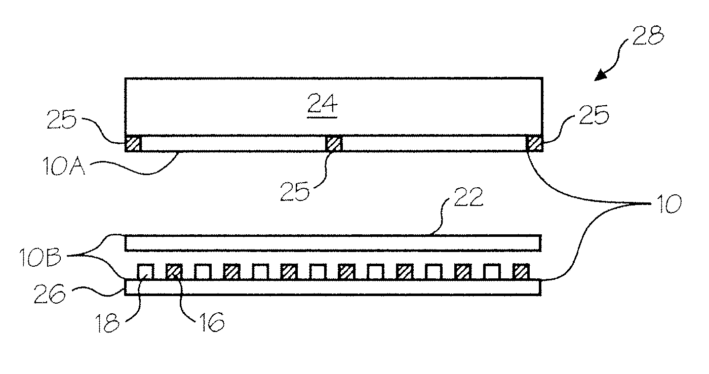
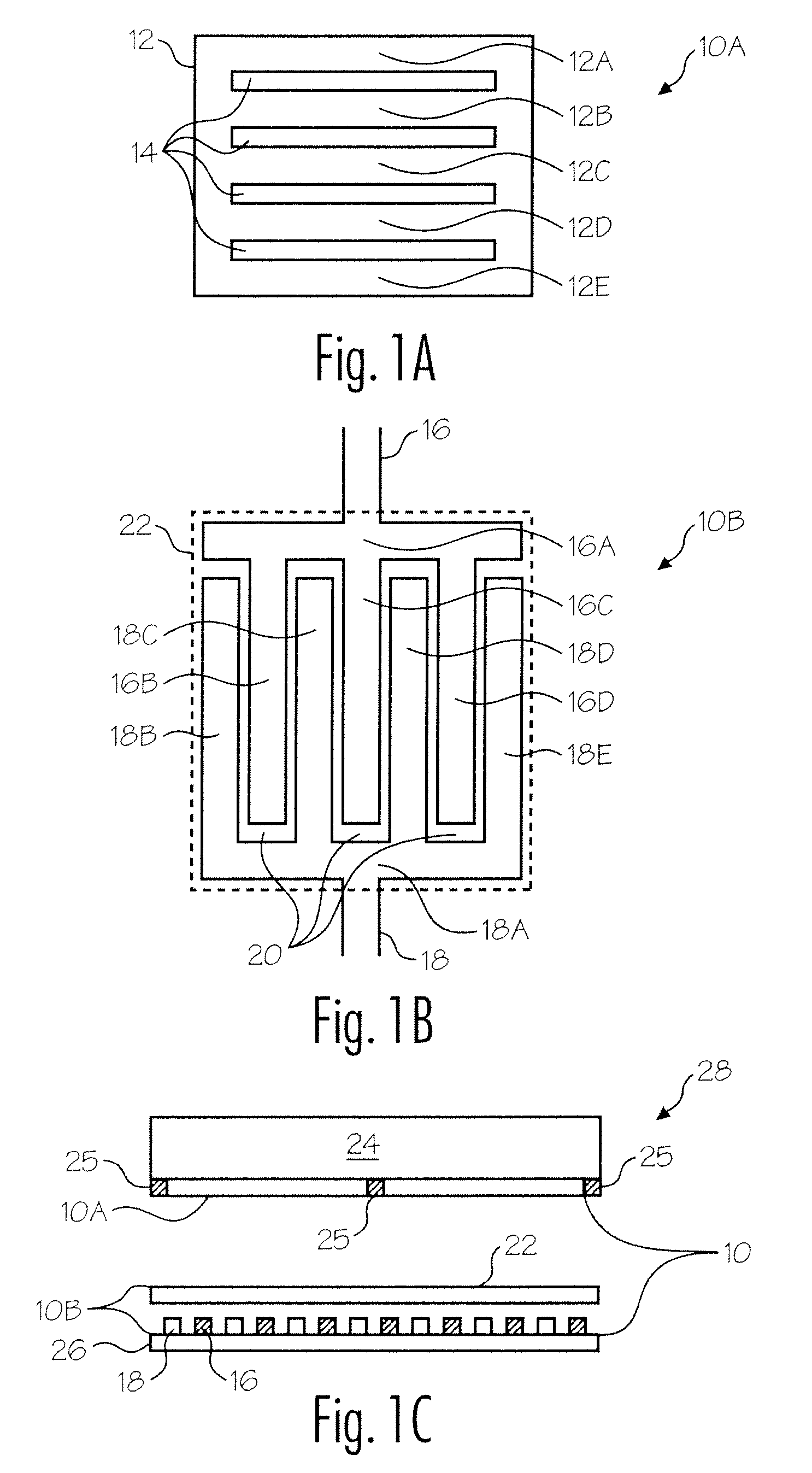
[0030]FIG. 1A is a plan view of a conductive region 10A of a switch 10, as show in cross section in FIG. 1C. FIG. 1B is a plan view of a conductive region 10B of switch 10. As shown in FIG. 1C, conductive region 10A is vertically aligned with conductive region 10B. A single switch 10 may be formed by vertically aligning conductive region 10A with conductive region 10B, as shown in FIGS. 1A and 1B, however, as is evident, a plurality of such switches 10 are represented in FIG. 1C, each of such switches 10 including a conductive region 10A vertically aligned with a corresponding conductive region 10B. Those skilled in the art understand that conductive regions 10A and 10B, as well as switch 10 (and control pan...


PUM


Abstract

An input system is delineated comprising an array of touch regions. At least one touch region is aligned with a sensing structure. The sensing structure comprises a first conductive region; a second conductive region aligned with the first conductive region, the second conductive region including a first conductive pattern forming a first switch terminal and a second conductive pattern forming a second switch terminal, the first conductive pattern separated by a space from the second conductive pattern; and a third conductive region between the first conductive region and the second conductive region, the third conductive region electrically coupling the first switch terminal to the second switch terminal to provide a first indication when the switch is open and a second indication when the switch is closed. Also delineated is a control panel including a plurality of such switches, as well as an appliance including such a control panel.

Description

CROSS-REFERENCE TO RELATED APPLICATIONS[0001]This application is a continuation-in-part of and claims priority to U.S. patent application Ser. No. 11 / 218,854, filed Sep. 2, 2005, which is filed in the name of the same inventor and incorporated herein by reference.BACKGROUND OF THE INVENTION[0002]1. Field of the Invention[0003]The present invention relates to switches and, more particularly, to switch arrays and systems employing the same to enhance system reliability and control.[0004]2. Description of the Related Art[0005]As used herein, the term “membrane switch” means a switch including a plurality of conductive regions with at least one of the conductive regions located on a layer of flexible material.[0006]Current membrane switches may include a first conductive region on a first layer of material aligned over a second conductive region on a second layer of material. A flexible material may be used for one or both of the first and second layers. One of the conductive regions ma...

Claims


Application Information

Patent Timeline
Patent Type & Authority Patents(United States)
IPC IPC(8): H01H1/10
CPCH01H13/78H01H13/785H01H13/79H01H2203/02H01H2227/006H01H2227/036H01H2229/004H01H2239/01H01H2203/022
Inventor PARKINSON, WAYNE
Owner ALMAX MFG CORP
Why Eureka
Try Eureka