Method of designing fold lines in sheet material

a technology of folding lines and sheet materials, applied in the direction of forging/pressing/hammering apparatus, instruments, handling devices, etc., can solve the problems of accumulation of tolerance errors, difficult control of bend locations, and significant cumulative tolerance errors in bending

Inactive Publication Date: 2008-10-21
IND ORIGAMI INC CA US
View PDF91 Cites 30 Cited by
  • Summary
  • Abstract
  • Description
  • Claims
  • Application Information

AI Technical Summary

Problems solved by technology

A commonly encountered problem in connection with bending sheet material is that the locations of the bends are difficult to control because of bending tolerance variations and the accumulation of tolerance errors.
The second bend, however, often is positioned based upon the first bend, and accordingly, the tolerance errors can accumulate.
Since there can be three or more bends which are involved to create the chassis or enclosure for the electronic components, the effect of cumulative tolerance errors in bending can be significant.
The problem of controlling the positioning of bend lines, of course, can occur in connection with may other three-dimensional products.
The bend forming techniques of such prior slitting-based systems may, however, significantly weaken the resulting structure.
Additionally, IOI's new slit-based bending designs result in structures that may be more rigid than traditionally bent structures that are un-slit.
While it is possible to draw IOI's new and improved slit configurations with the standard sketch tools of conventional computer-aided design (CAD) systems, a CAD user may find that drawing, locating, scaling and shaping individual compound-shaped slits that constitute IOI's slit configurations rather repetitive and challenging.

Method used


Image

  • Method of designing fold lines in sheet material
  • Method of designing fold lines in sheet material
  • Method of designing fold lines in sheet material

Examples


Embodiment Construction

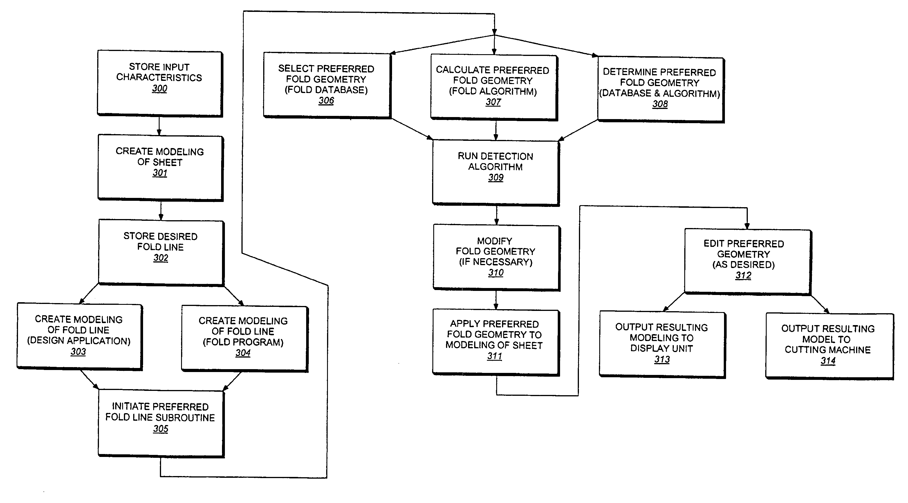
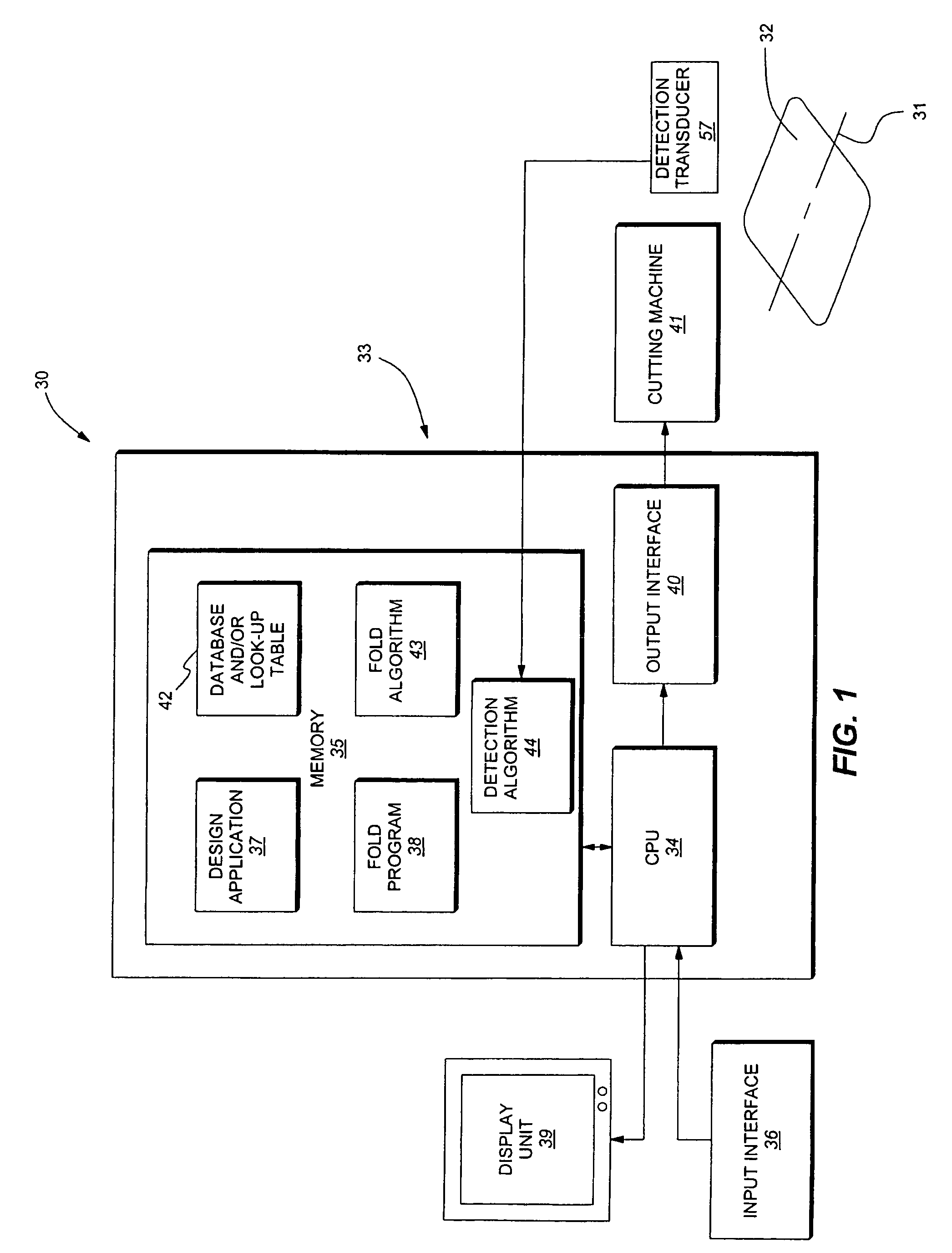
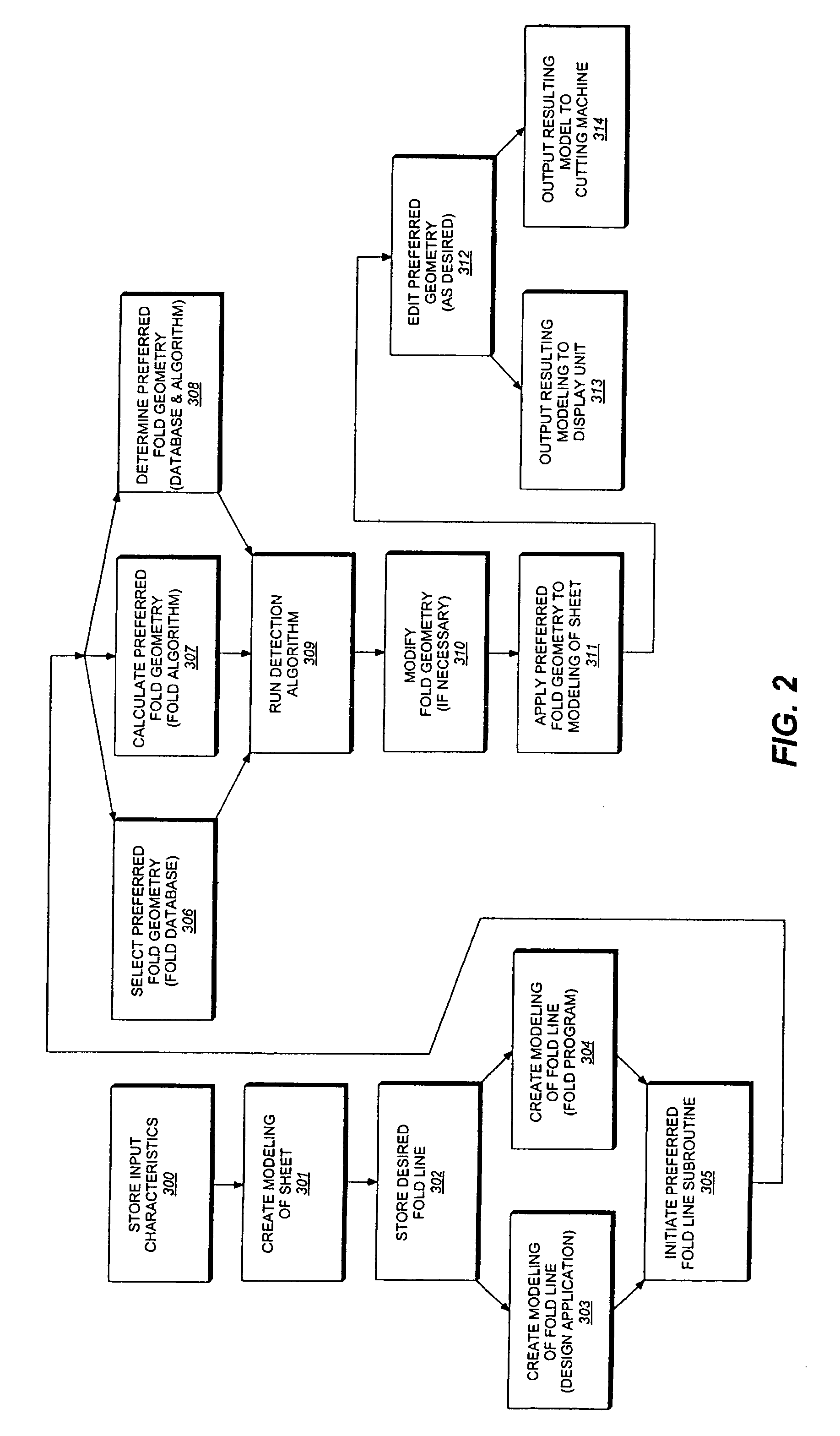
[0034]Reference will now be made in detail to the preferred embodiments of the invention, examples of which are illustrated in the accompanying drawings. While the invention will be described in conjunction with the preferred embodiments, it will be understood that they are not intended to limit the invention to those embodiments. On the contrary, the invention is intended to cover alternatives, modifications and equivalents, which may be included within the spirit and scope of the invention as defined by the appended claims.

[0035]The present invention is directed to methods, computer program products and systems for designing one or more desired fold lines for a non-crushable sheet of material utilizing various fold geometries and configurations including, but not limited to, those disclosed by U.S. patent application Ser. No. 09 / 640,267, filed August filed Aug. 17, 2000, entitled METHOD FOR PRECISION BENDING OF A SHEET OF MATERIAL AND SLIT SHEET THEREFOR and now U.S. Pat. No. 6,48...


PUM

PropertyMeasurementUnit
stress concentrationaaaaaaaaaa
thicknessaaaaaaaaaa
strap densityaaaaaaaaaa

Abstract

A method includes defining a desired fold line in sheet material and populating the fold line with a fold geometry including cut zones that define connected zones, whereby upon folding the material produces edge-to-face engagement of the material on opposite sides of the cut zones. Alternatively, the method includes storing cut zone configurations and connected zone configurations, defining a desired fold line, selecting a cut zone and / or a connected zone, locating a preferred fold geometry, including the cut zone and the connected zone, along the fold line, and relocating, rescaling and / or reshaping the preferred fold geometry to displace, add and / or subtract at least one of the connected zones, whereby upon folding the material produces edge-to-face engagement of the material on opposite sides of the cut zones. Also, a computer program product and a system configured for implementing the method.

Description

RELATED APPLICATIONS[0001]This application is a Continuation-in-Part of U.S. patent application Ser. No. 10 / 795,077, filed Mar. 3, 2004 and entitled SHEET MATERIAL WITH BEND CONTROLLING DISPLACEMENTS AND METHOD FOR FORMING THE SAME and now U.S. Pat. No. 7,152,450, which is a Continuation-in-Part of U.S. patent application Ser. No. 10 / 672,766, filed Sep. 26, 2003 and entitled TECHNIQUES FOR DESIGNING AND MANUFACTURING PRECISION-FOLDED, HIGH STRENGTH, FATIGUE-RESISTANT STRUCTURES AND SHEET THEREFOR and now U.S. Pat. No. 7,152,449, which is a Continuation-in-Part of U.S. patent application Ser. No. 10 / 256,870, filed Sep. 26, 2002 and entitled METHOD FOR PRECISION BENDING OF SHEET MATERIALS, SLIT SHEET AND FABRICATION PROCESS and now U.S. Pat. No. 6,877,349, which is a Continuation-in-Part of U.S. patent application Ser. No. 09 / 640,267, filed Aug. 17, 2000 and entitled METHOD FOR PRECISION BENDING OF A SHEET OF MATERIAL AND SLIT SHEET THEREFOR and now U.S. Pat. No. 6,481,259, the entire...

Claims


Application Information

Patent Timeline
Patent Type & Authority Patents(United States)
IPC IPC(8): G06F17/50B21D28/00B21D5/00
CPCB21D5/00B21D11/20
Inventor DURNEY, MAX W.PENDLEY, ALAN D.
Owner IND ORIGAMI INC CA US
Why Eureka
Try Eureka