Bridging device

a technology of bridging device and bridge, which is applied in the direction of bridge type, vehicles, transportation items, etc., can solve the problems of large mounting area, known automatic ramps, and most automated access ramps

Inactive Publication Date: 2008-11-18
FULLERTON KEVIN JOHN +1
View PDF29 Cites 14 Cited by
  • Summary
  • Abstract
  • Description
  • Claims
  • Application Information

AI Technical Summary

Benefits of technology

[0019]The key slot is preferably angled at a rear end to create a curve to the end plates when extended, therefore giving the bridging device in its extended position a pre-camber for visual appeal and psychological reassurance of its strength.

Problems solved by technology

Known automatic ramps have several inherent problems.
Firstly, in their retracted state they are bulky and require a large area to mount.
Some of them-are also heavy which is undesirable in terms of speed and fuel efficiency if the retractable ramp is mounted on a transport vehicle.
Most automated access ramps, due to their size, are economically unviable for retrofitting to existing transport systems.
Retrofitting is made more difficult by the various structural constraints associated with mounting the ramps.
Additionally, most devices need to be fully extended to perform the function of a ramp and can be unwieldy if the gap to be bridged is small.
This articulated ramp assembly is awkward and very bulky, particularly when it is attached below the carriage floor of a train where space below the floor is limited and the aerodynamics and weight balance of the train could be affected by such a structure mounted to the carriages.
Furthermore, the articulated segments forming the ramp body of WO 99 / 52738 move in a scissor and clamping motion which present safety problems to the operator and the public.
This scissor and clamping motion easily runs the risk of rendering the function of the ramp inoperable by the invasion of foreign objects, by accident or sabotage.
This could result in disruption to transport schedules and possible physical injury.

Method used


Image

  • Bridging device
  • Bridging device
  • Bridging device

Examples


Embodiment Construction

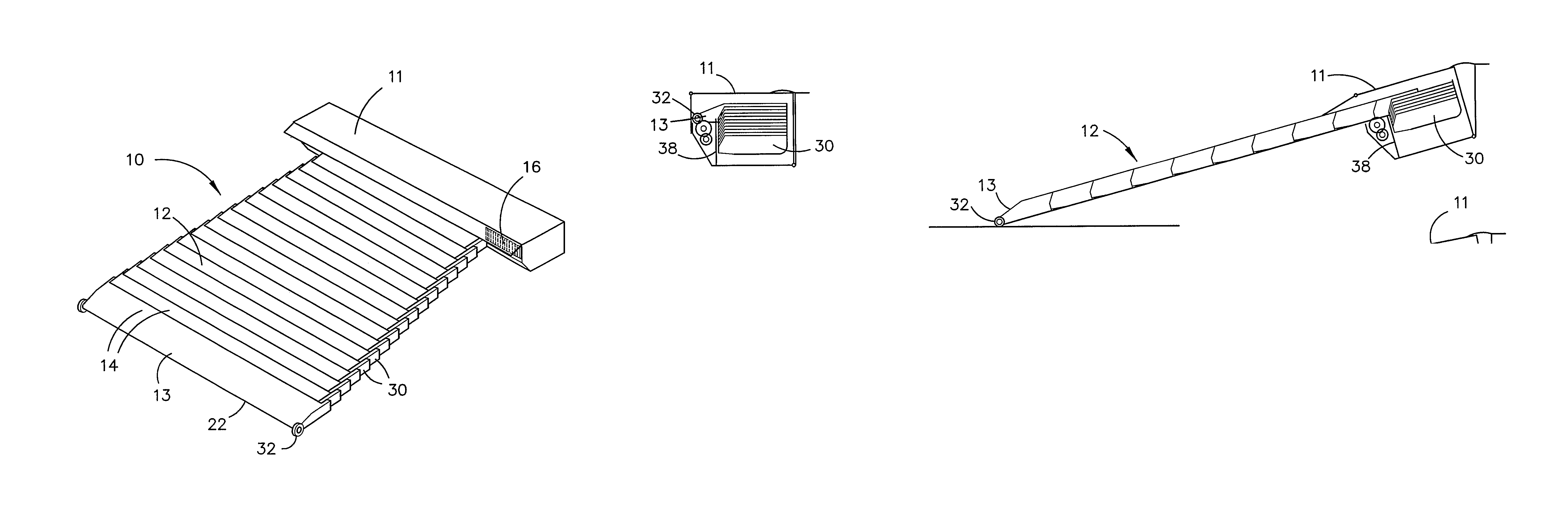
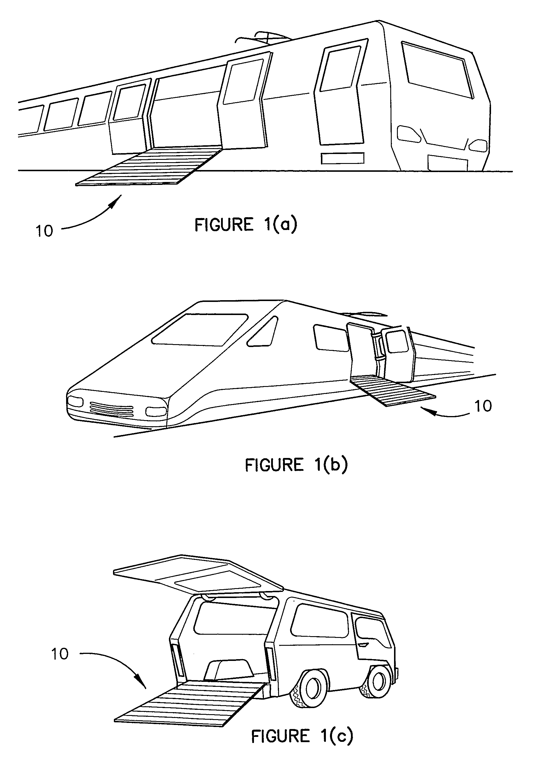
[0044]The Figures illustrate a bridging device 10 that in its preferred use is adapted to be mounted at or under a door opening of a vehicle. Such a vehicle could be a train, tram, bus, taxi, water vehicles such as ferries, or private road vehicles.

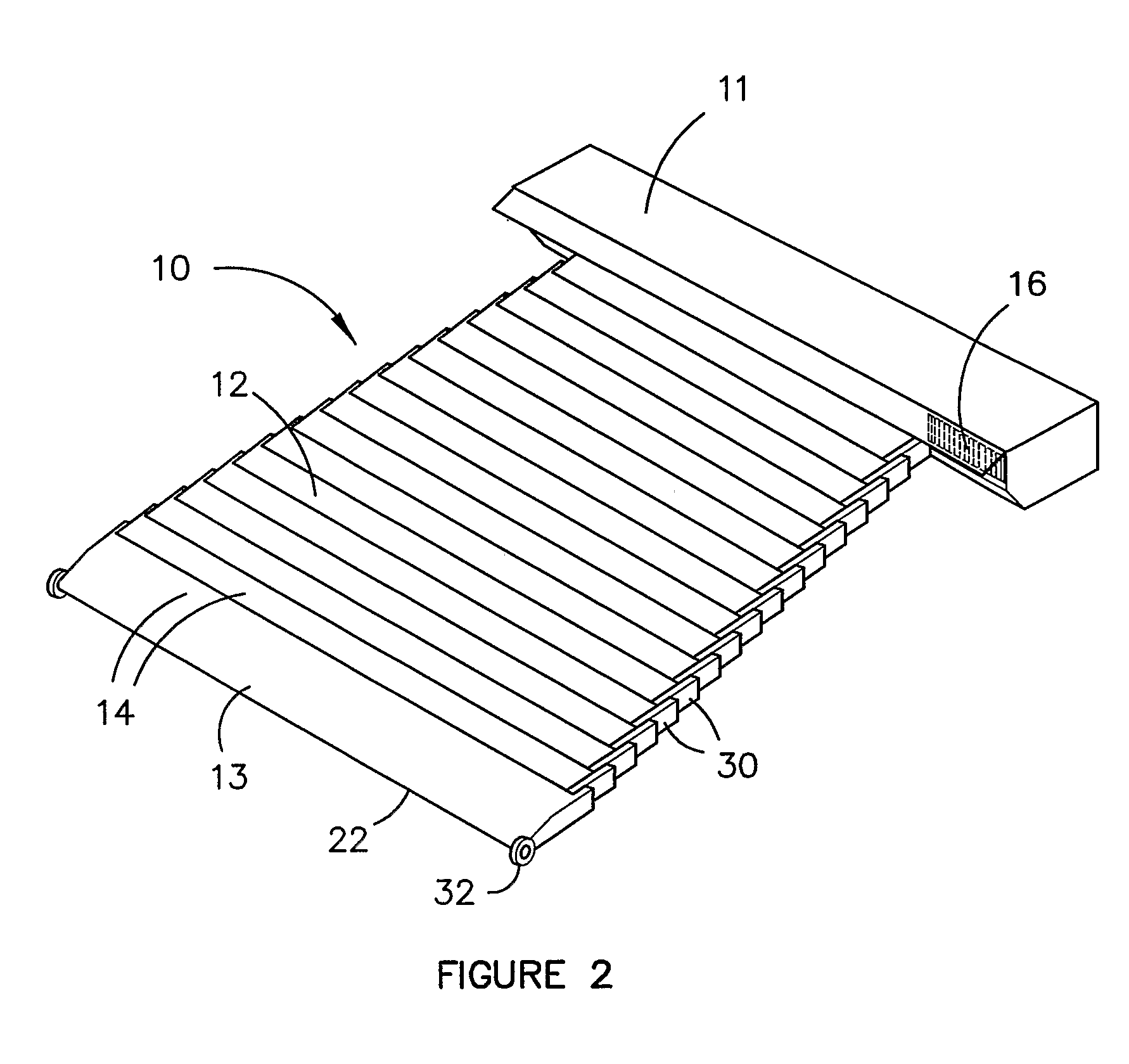
[0045]The bridging device 10 comprises a housing 11 from which, as illustrated in FIG. 2, a bridging surface, or ramp 12, telescopically extends. The ramp 12 is designed to bridge a gap between two points and specifically between the point at which the housing 11 is mounted and a point at the opposite side of the gap. Furthermore, the gap may be between: two spaced surfaces at the same level or surfaces of uneven height. A leading edge 13 of the ramp may be supported on the opposite surface or may remain unsupported, extending in a cantilevered fashion from the housing.

[0046]The ramp 12 comprises a stack of interjoined beams 14 that slide out of the housing one over the other to telescopically extend from the retracted position, as illust...


PUM


Abstract

A bridging device (10) for providing a bridging surface (12) between two points comprising a stack of interjoined beams (14) housed in a retracted position in a housing (11) mounted at a first point; and a drive system that drives the beams (14) to slide one over the other to telescopically extend out of the housing (11) from the retracted position to an extended position to thereby form a bridging surface (12) to a second point.

Description

CROSS-REFERENCE TO RELATED APPLICATIONS[0001]This application is an U.S. national phase application under 35 U.S.C. §371 based upon co-pending International Application No. PCT / AU2005 / 000652 filed on May 9, 2005. Additionally, this U.S. national phase application claims the benefit of priority of co-pending International Application No. PCT / AU2005 / 000652 filed on May 9, 2005 and Australia Application No. 2004902470 filed on May 10, 2004. The entire disclosures of the prior applications are incorporated herein by reference. The international application was published on Nov. 17, 2005 under Publication No. WO 2005 / 108161.BACKGROUND OF THE INVENTION[0002]Automated access ramps and other bridging devices bridge gaps and provide a pathway for persons or vehicles to cross.[0003]Automatic ramps are very useful in the public and private transport industry. The ramps allow access onto and off trains and road vehicles for both enabled and disabled commuters as well as small vehicles such as b...

Claims


Application Information

Patent Timeline
Patent Type & Authority Patents(United States)
IPC IPC(8): E01D15/22E01D15/10A61G3/06B60P1/43B61D23/02B62D25/22B63B27/14B65G69/28
CPCA61G3/063B60P1/431B63B27/143B61D23/025A61G2003/067A61G3/067
Inventor FULLERTON, KEVIN JOHNSCHACHT, THEODOR REINHARDT
Owner FULLERTON KEVIN JOHN
Why Eureka
Try Eureka