Method of heat shielding an inner tube

a technology of heat shielding and inner tubes, which is applied in the direction of thermal insulation, rigid pipes, non-disconnectible pipe joints, etc., can solve the problem of expensive production of protective sheathes

Active Publication Date: 2008-11-18
PRATT & WHITNEY CANADA CORP
View PDF19 Cites 18 Cited by
  • Summary
  • Abstract
  • Description
  • Claims
  • Application Information

AI Technical Summary

Problems solved by technology

Such protective sheathes are costly to produce and sometimes present dynamic issues.

Method used


Image

  • Method of heat shielding an inner tube
  • Method of heat shielding an inner tube
  • Method of heat shielding an inner tube

Examples


Embodiment Construction

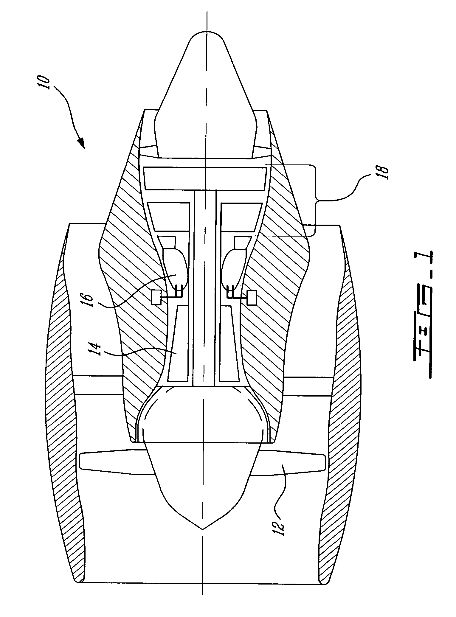
[0017]FIG. 1 illustrates a gas turbine engine 10 of a type preferably provided for use in subsonic flight, generally comprising in serial flow communication a fan 12 through which ambient air is propelled, a multistage compressor 14 for pressurizing the air, a combustor 16 in which the compressed air is mixed with fuel and ignited for generating an annular stream of hot combustion gases, and a turbine section 18 for extracting energy from the combustion gases.

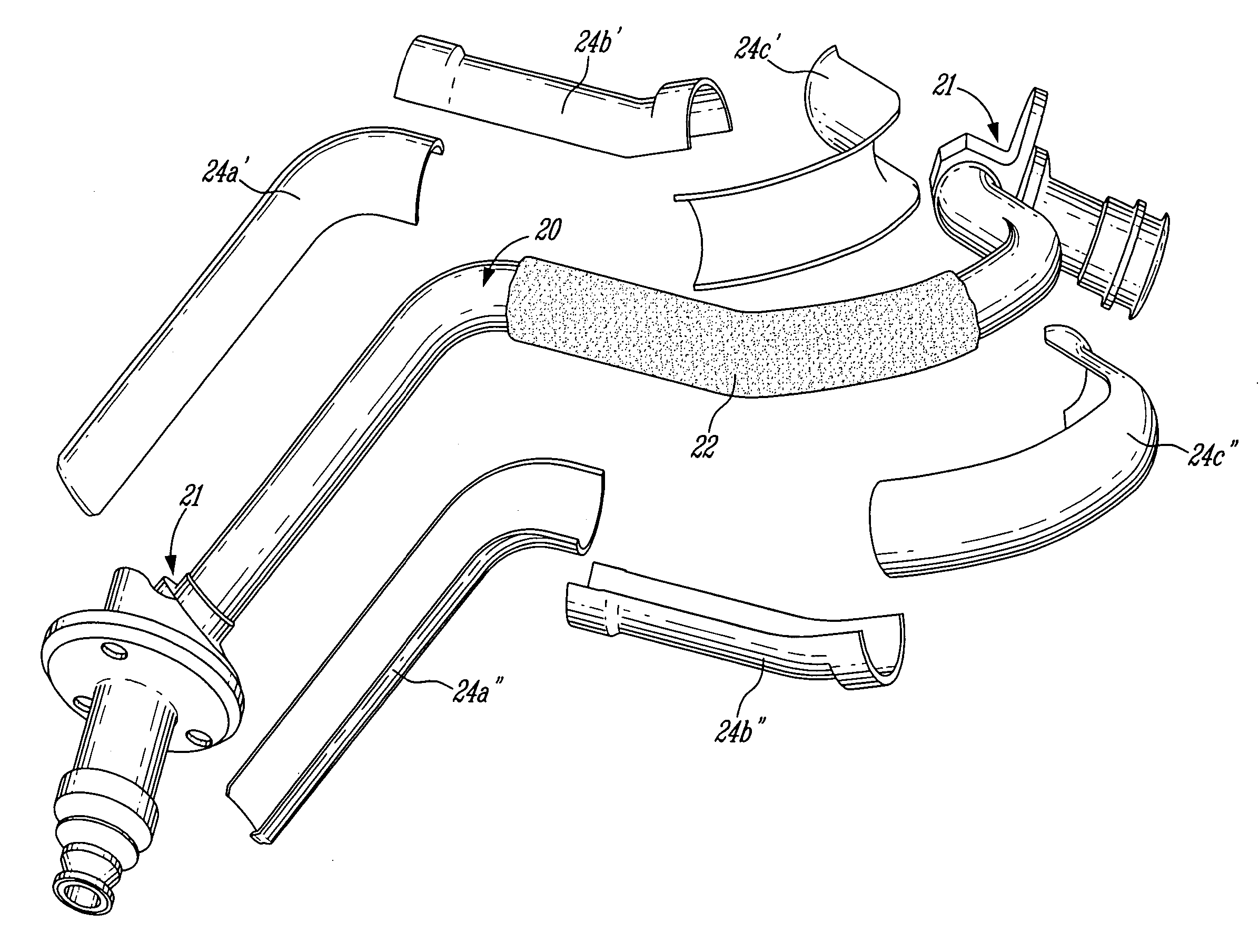
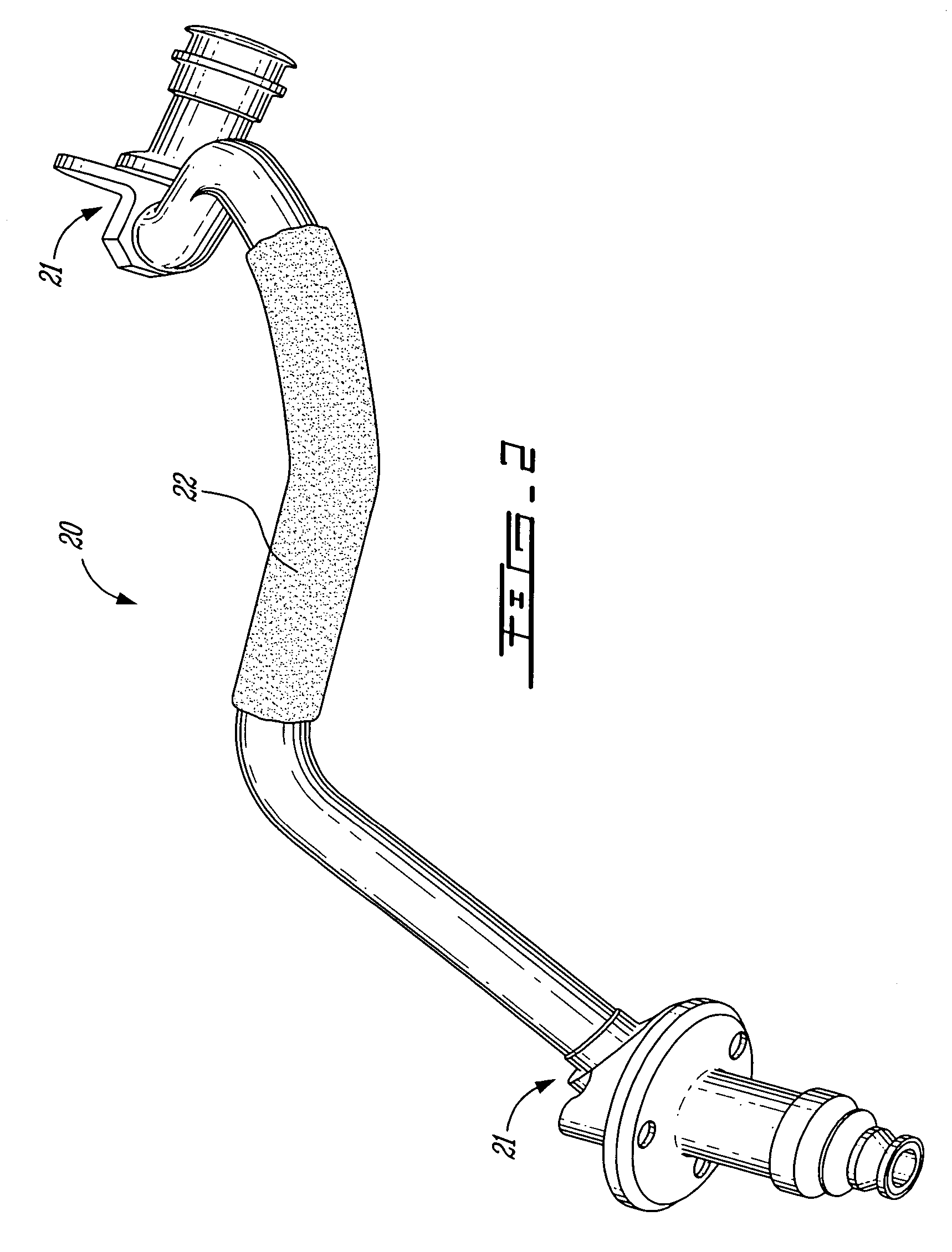
[0018]FIG. 2 illustrates a typical oil-carrying tube 20 provided with ferrules or fittings 21 at opposed ends thereof. The oil tube 20 is representative of the non-linear oil tubes typically mounted next to the combustor 16 for carrying oil to various lubricated engine parts. Such tubes are exposed to hot temperatures and, thus, often require insulation. Accordingly, a tube insulation liner 22 covers oil tube 20 for thermally shielding same against the hot surrounding environment.

[0019]Rather than using a sheet metal to form a ...


PUM

PropertyMeasurementUnit
diameteraaaaaaaaaa
lengthaaaaaaaaaa
length L2aaaaaaaaaa

Abstract

A protective sheath for a fluid-carrying tube is made from a larger tube cut into longitudinal tube segments and slice into opposed halves before being re-secured together about the fluid-carrying tube. Slip joints are preferably provided between adjoining outer tube segments.

Description

TECHNICAL FIELD[0001]The invention relates generally to tube insulation and, more particularly, to tube heat shields and methods for thermally shielding tubes.BACKGROUND OF THE ART[0002]Fluid-carrying tubes, such as gas turbine engine oil tubes, often require insulation when exposed to hot temperature environments. Insulation sheathes typically comprise a protective metal sheet that surrounds an insulating material covering the fluid-carrying tube. The protective sheathes are typically formed of separate sheet metal halves resistance welded together about the inner pipe and the insulation material. Such protective sheathes are costly to produce and sometimes present dynamic issues.[0003]Accordingly, there is a need to provide an improved way of heat shielding tubes exposed to high temperatures.SUMMARY OF THE INVENTION[0004]It is therefore an object of this invention to overcome the aforementioned drawbacks of the prior art.[0005]In one aspect, the present invention provides a method...

Claims


Application Information

Patent Timeline
Patent Type & Authority Patents(United States)
IPC IPC(8): B21D53/06B21C37/06B23P11/00
CPCF16L9/17F16L59/024Y10T29/49361Y10T29/49391Y10T29/49893Y10T29/49789
Inventor STASTNY, HONZALIM, ENG
Owner PRATT & WHITNEY CANADA CORP
Why Eureka
Try Eureka