Swivel ball bearing

a ball bearing and swivel technology, applied in the direction of bearings, bearings, shafts and bearings, etc., can solve problems such as ball bearing assemblies jamming

Inactive Publication Date: 2008-11-25
BRODOWSKI JOHN
View PDF8 Cites 8 Cited by
  • Summary
  • Abstract
  • Description
  • Claims
  • Application Information

AI Technical Summary

Problems solved by technology

A full complement of ball bearings would impede the balls' free movement and cause that ball bearing assembly to jam.

Method used


Image

  • Swivel ball bearing
  • Swivel ball bearing
  • Swivel ball bearing

Examples


Embodiment Construction

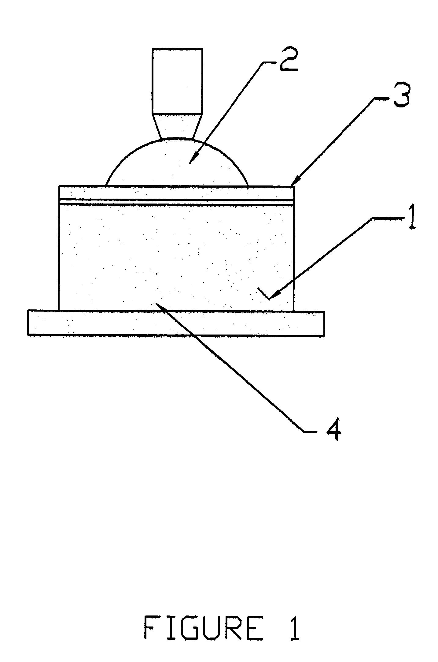
[0021]The device shown on FIG. 1 includes housing 1; shaft and ball 2; cover 3; and ball bearings 4 (not shown on FIG. 1).

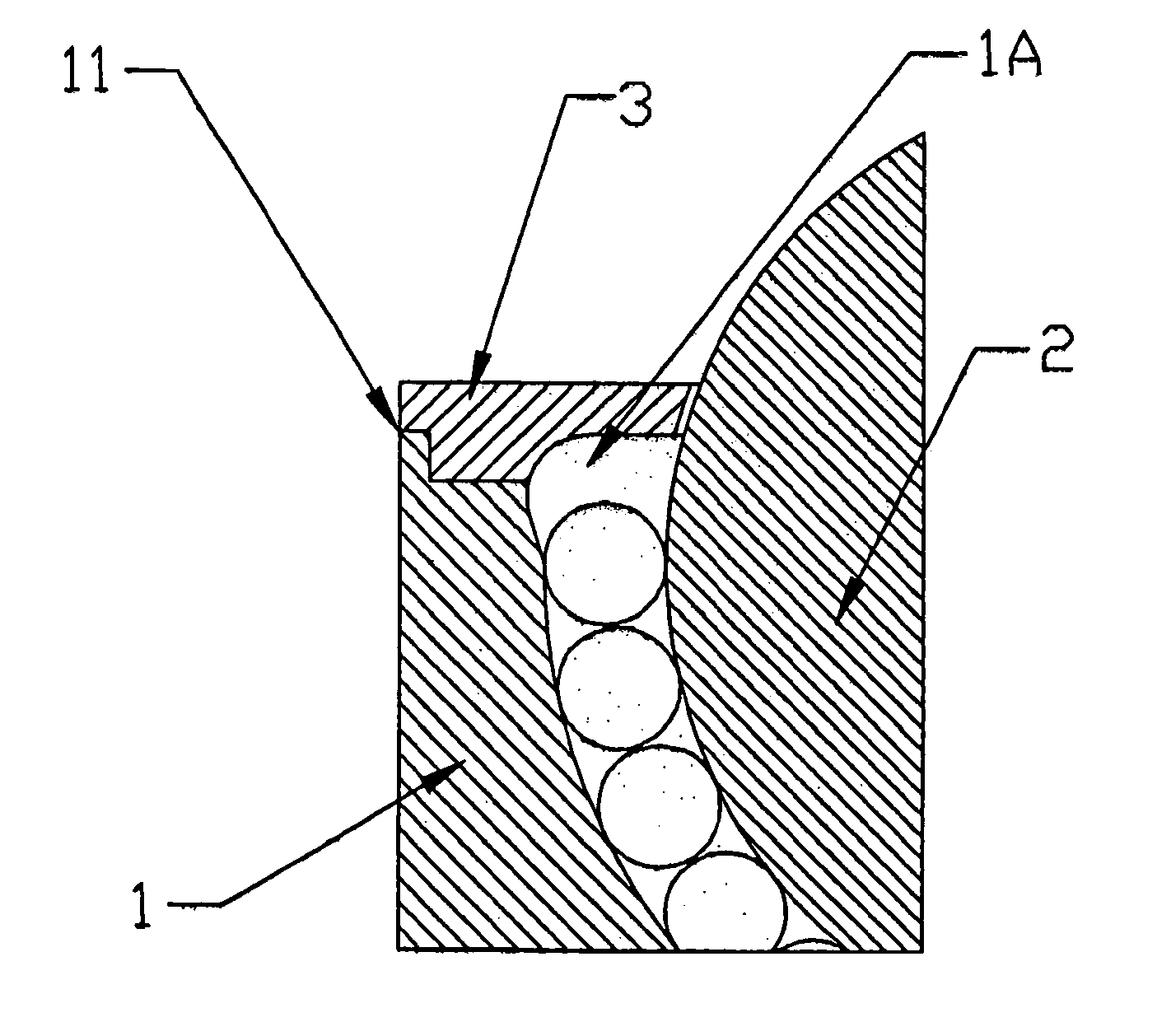
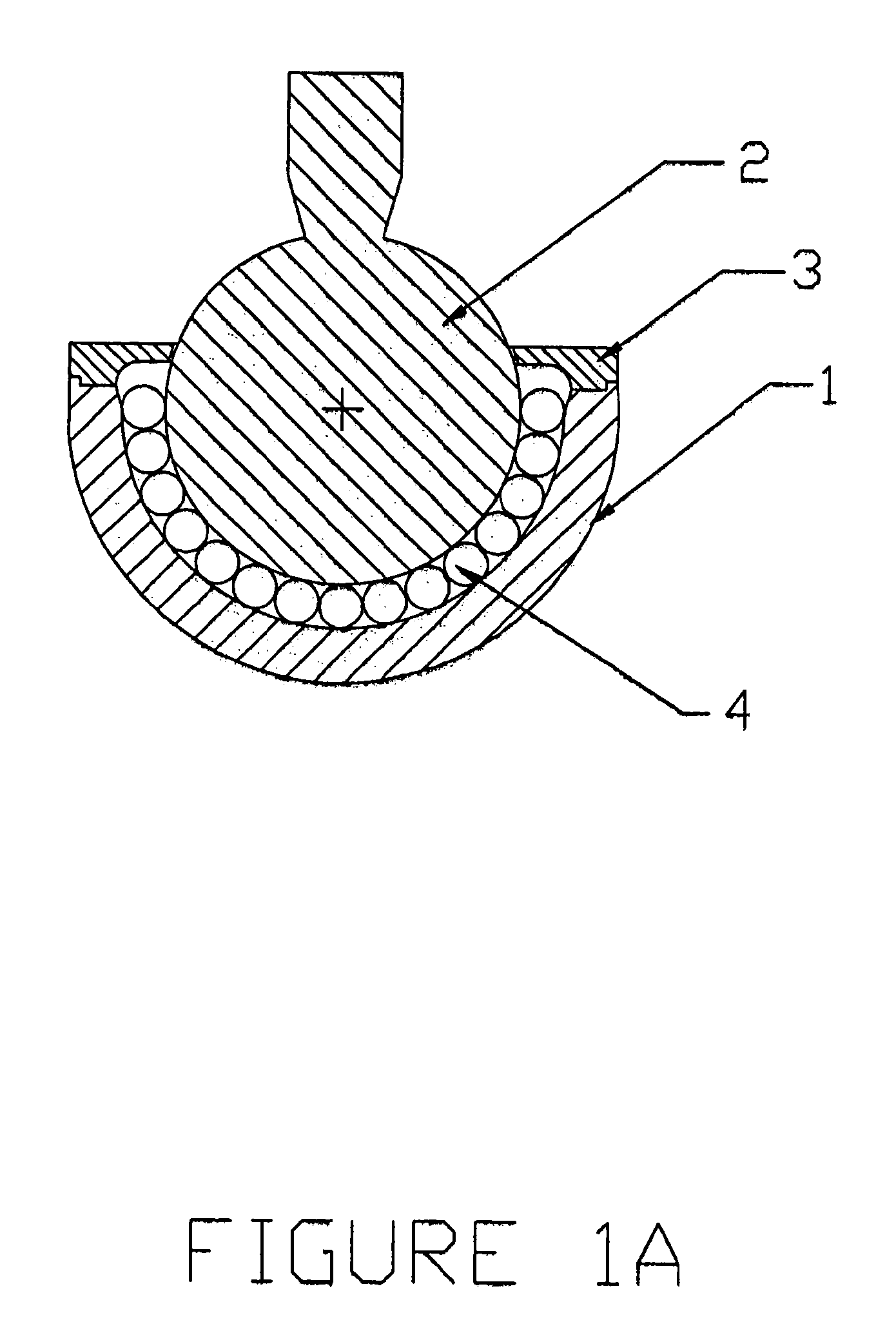
[0022]The device shown on FIG. 1A is identical to the device shown on FIG. 1, except for shape of housing 1. Operationally, the two devices behave identically. Cross-section of the device is shown on FIG. 1A, and an exploded view of the device is shown on FIG. 2. FIG. 1A shows ball and shaft 2, resting on ball bearings 4. Ball bearings 4, are in contact with concave seat machined in housing 1. In order for any bearing device to work properly, ball bearings must be allowed to rotate and translate in the channel. Prior art bearing devices accommodate ball bearings' rotation and translation in specially designed channels. The device shown on FIGS. 1 and 1A, having a unique free zone channel, accomplishes the required criteria for free ball bearing movement. The free zone channel can be machined in either housing, FIG. 3 and FIG. 3A, as indicated by arrow 1A, or can ...


PUM


Abstract

A swivel bearing assembly consists of an outer housing, a ball and a shaft, a cover, and ball bearings, wherein a free-zone channel.A free-zone channel allows the ball bearings to roll freely in the assembly as they follow the motion of the ball and shaft. The ball bearings eliminate friction between ball and outer housing. The ball and shaft can have simultaneous rotational and angular motion. Only unidirectional load can be applied to the bearing in the direction of the mounting surface.

Description

BACKGROUND OF THE INVENTION[0001]1. Field of the Invention[0002]The present invention relates to ball joints having ball bearings as a friction-reducing medium and, more particularly, to the ball bearings' ability to freely circulate without being trapped between the concave portion of housing and large ball.[0003]2. Description of Prior Art[0004]Various kinds of prior art ball joints with ball bearings have been proposed and developed.[0005]U.S. Pat. No. 6,409,388 to Lin[0006]U.S. Pat. No. 5,096,308 to Sundseth[0007]U.S. Pat. No. 5,076,412 to Huber—In this invention, the ball bearings have a channel and roll in one plane only.[0008]However, the typical prior art designs do not allow the ball bearings (small balls) to freely circulate between the concave housing and large ball.[0009]Prior art ball joints with a full complement of ball bearings which completely fill the space between the housing and the large ball, and without a special channel which would permit their free movement,...

Claims


Application Information

Patent Timeline
Patent Type & Authority Patents(United States)
IPC IPC(8): F16C11/06
CPCF16C11/0619Y10T403/32631Y10T403/32737
Inventor BRODOWSKI, JOHN
Owner BRODOWSKI JOHN
Why Eureka
Try Eureka