Modular prosthesis and locking nut therefor

a technology of modular prosthesis and locking nut, which is applied in the field of modular prosthesis, can solve the problems of device disclosure, stress being non-uniformly transferred, and not fully addressing the risk of fracture in vivo

Active Publication Date: 2008-11-25
DEPUY PROD INC
View PDF46 Cites 14 Cited by
  • Summary
  • Abstract
  • Description
  • Claims
  • Application Information

AI Technical Summary

Benefits of technology

[0003]Many modular prosthetic systems are available that couple a distal stem to a proximal component. Often this coupling is accomplished using a Morse-type taper joint with the frusto-conical male portion of the joint being formed on one component while the female frusto-conical cavity is formed on the other component. In several such devices a fastener is utilized to aid the taper joint in remaining associated in vivo.

Problems solved by technology

However, the device disclosed therein does not fully address the risk of fracture in vivo.
Often the fasteners utilized to couple components of modular prosthesis together are configured to non-uniformly transfer stresses experienced by the fastener to the adjacent prosthesis components.
When a standard locking nut is screwed onto a threaded shaft disposed in such a cavity, the nut (when the device is under stress) may contact the bottom surface of the cavity at a single point resulting in the stresses being non-uniformly transferred.
This non-uniform distribution of stresses may induce the prosthesis components to fracture under stress.

Method used


Image

  • Modular prosthesis and locking nut therefor
  • Modular prosthesis and locking nut therefor
  • Modular prosthesis and locking nut therefor

Examples


Embodiment Construction

[0024]For the purposes of promoting an understanding of the principles of the invention, reference will now be made to the embodiments illustrated in the drawings and described in the following written specification. It is understood that no limitation to the scope of the invention is thereby intended. It is further understood that the present invention includes any alterations and modifications to the illustrated embodiments and includes further applications of the principles of the invention as would normally occur to one skilled in the art to which this invention pertains.

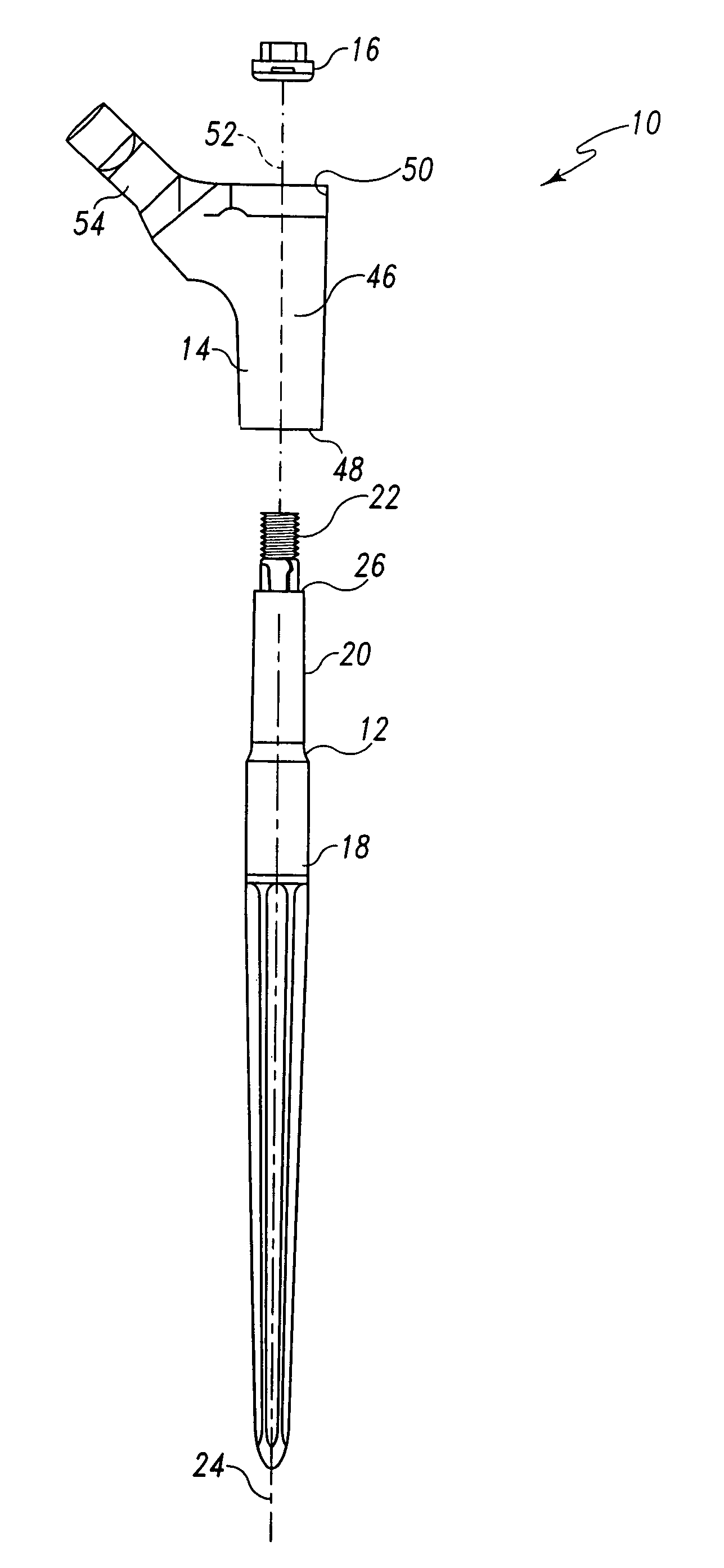
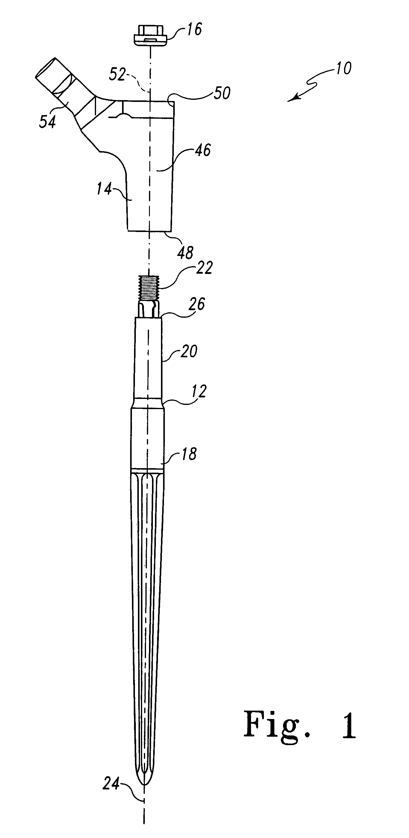
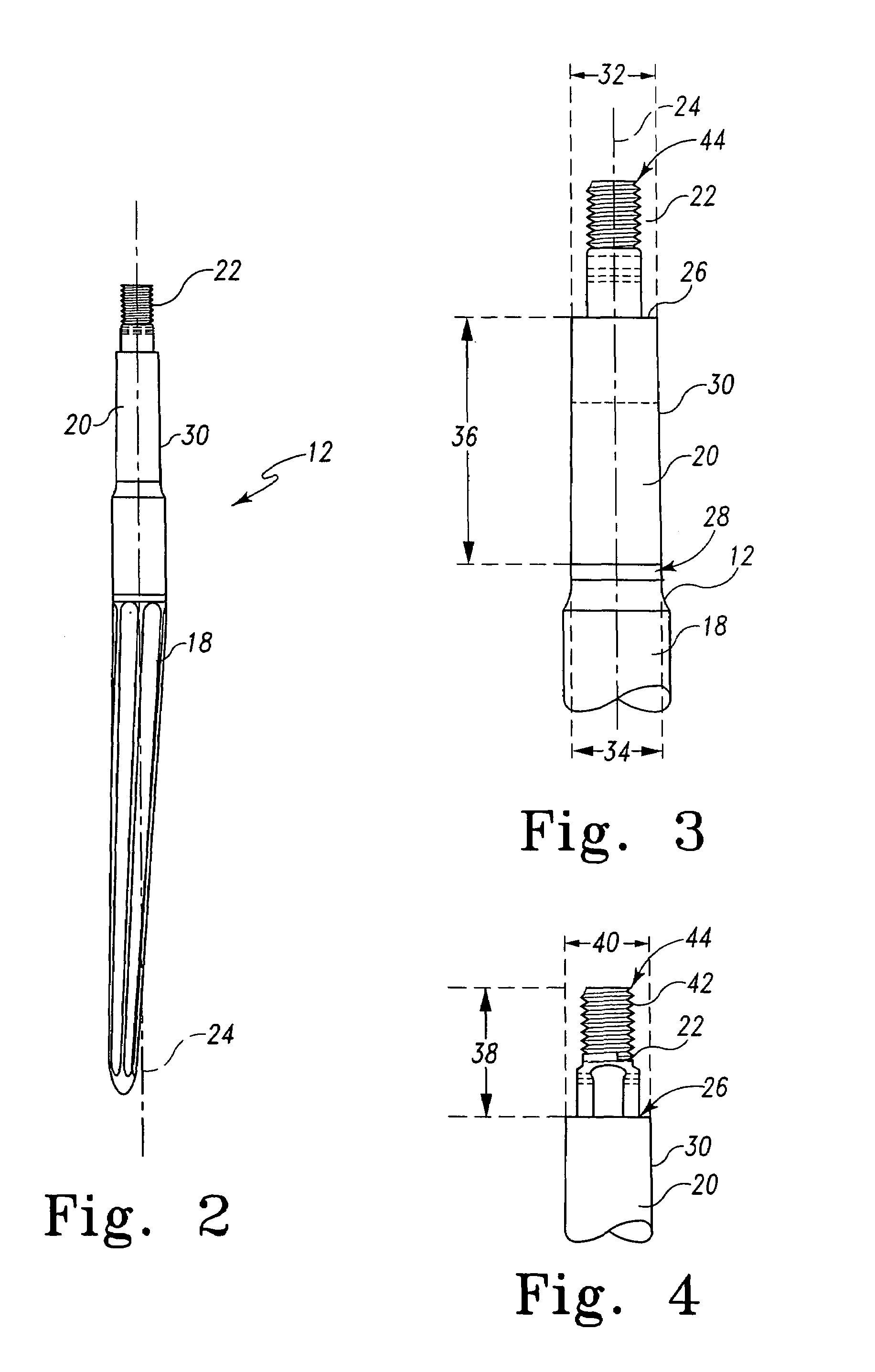
[0025]As shown for example, in FIGS. 1-11, a modular prosthesis 10 includes a distal stem component 12, a proximal body component 14 and a locking nut 16. The illustrated modular prosthesis 10 includes components that can be mated to form a component of a hip prosthesis for attachment to the femur of a patient. While not illustrated, the modular prosthesis 10 may also include a plurality of differently sized hea...


PUM


Abstract

A modular prosthesis is provided having a first and second prosthesis component and a locking nut. The first prosthesis component is configured to include a mating surface and a threaded shaft extending from the mating surface. The locking nut is formed to include a distal end having a shaped surface. The second prosthesis component is configured to include a mating surface, a nut-receiving cavity and a bore. The mating surface of the second prosthesis component is configured to mate with the mating surface of the first prosthesis component. The nut-receiving cavity is configured to receive the locking nut therein and to have a shaped bottom wall configured to engage the shaped surface of the locking nut. The bore communicates with the nut-receiving cavity through the shaped bottom wall and the mating surface and is sized to receive the threaded shaft therethrough. The threaded shaft, locking nut, bore and cavity are configured so that when the threaded shaft of the first prosthesis extends through the bore and the locking nut is received in the nut-receiving cavity and tightened onto the threaded shaft, the distal end of the locking nut is urged into engagement in multiple locations with the bottom wall of the cavity and the mating surfaces of the first and second components are urged into engagement.

Description

BACKGROUND AND SUMMARY[0001]This invention relates generally to modular prosthesis and more particularly to modular prosthesis having a plurality of distal components adapted to be mounted to a proximal component with a locking nut.[0002]In many total joint devices, longer stems are employed in either more difficult cases or cases with abnormal anatomy. A distally modular stem is desirable since it allows positioning of the distal stem consistent with the patient's anatomy while independently positioning the proximal body in order to optimize the biomechanics. Firm locking of the proximal body and distal stem is critical to the success of such a modular stem. Two critical concerns to clinicians are that the components could disassociate or fracture in vivo.[0003]Many modular prosthetic systems are available that couple a distal stem to a proximal component. Often this coupling is accomplished using a Morse-type taper joint with the frusto-conical male portion of the joint being form...

Claims


Application Information

Patent Timeline
Patent Type & Authority Patents(United States)
IPC IPC(8): A61F2/32A61F2/36A61F2/00A61F2/30
CPCA61F2/30721A61F2/3662A61F2/3676A61F2002/30143A61F2002/30332A61F2002/30354A61F2002/30378A61F2002/30512A61F2002/30604A61F2002/30616A61F2002/30827A61F2002/30886A61F2002/3611A61F2002/3625A61F2002/3674A61F2002/3686A61F2220/0025A61F2220/0033A61F2230/0017A61F2/36A61F2/367A61F2002/30507
Inventor KHALILI, BRUCEROTH, NADINE
Owner DEPUY PROD INC
Why Eureka
Try Eureka