Crop header with draper canvas and a seal with an element of the cutter bar

a technology of which is applied in the field of crop headers with draper canvas and seals with cutter bars, can solve the problems of not being adopted and the arrangement has not been successful

Active Publication Date: 2009-01-06
MACDON INDS
View PDF5 Cites 136 Cited by
  • Summary
  • Abstract
  • Description
  • Claims
  • Application Information

AI Technical Summary

Benefits of technology

[0008]It is one object of the invention to provide a further design of header and particularly the draper canvas therefore which can assist in providing a seal between the canvas and the cutter bar,
[0022]the cutter bar including an element thereof extending rearwardly over the upper run of the draper canvas to a position rearwardly of the front edge of the upper run of the draper canvas and forwardly of the front end of the rollers and of the front edge of the support plate and engaging the upper surface of said strip on the draper canvas so that the engagement between the element of the cutter bar and the upper surface of the strip forms a seal to inhibit entry between the cutter bar and the draper canvas of materials carried by the cut crop.
[0032]Preferably the draper canvas has a folded edge at least at the front edge and more preferably the folded edge is folded back on the outer surface of the fabric material for enhanced stiffness.
[0033]Preferably the draper canvas includes a second strip on the rear edge located and arranged symmetrically relative to the strip on the front edge for reversibility of the canvas when worn.
[0035]Preferably each of the beads is arranged so as to lie on the inner surface opposite to the respective strip within the width of the respective strip. The front bead therefore has no effect since it is located underneath the strip forwardly of the roller and support plate but the rear bead is a guide bead for cooperating with a groove in the roller. The symmetrical arrangement again allows reversibility.

Problems solved by technology

This arrangement has not been successful and has not been adopted since it failed to provide the expected improvements over the Talbot arrangement.

Method used


Image

  • Crop header with draper canvas and a seal with an element of the cutter bar
  • Crop header with draper canvas and a seal with an element of the cutter bar
  • Crop header with draper canvas and a seal with an element of the cutter bar

Examples


Embodiment Construction

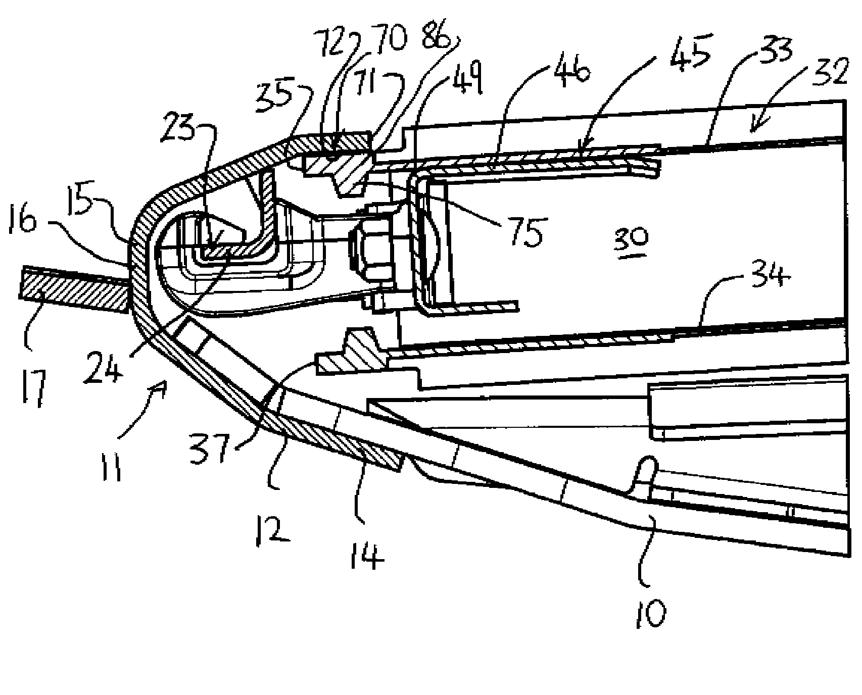
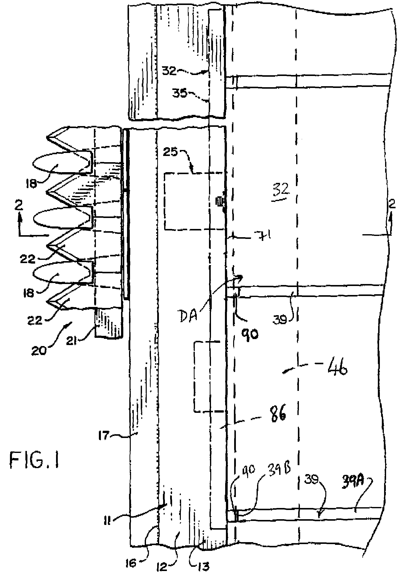
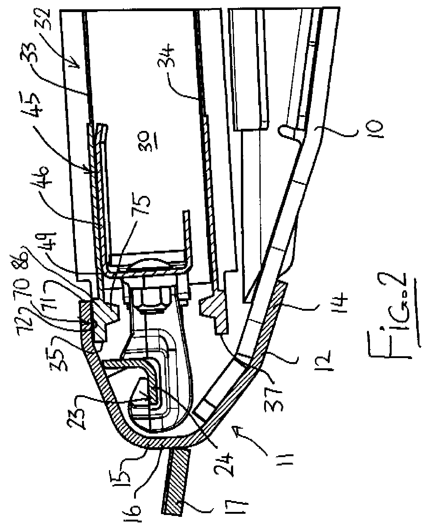
[0053]Only those parts of the header which are of importance to the present invention are shown in the above figures of the present application and the remaining parts of the header including the frame structure, drives, ground wheels and the like are omitted as these will be well known to one skilled in the art. The present invention is concerned with the area of co-operation between the front and rear edges of the draper with the cutter bar and with the rear header plate respectively and therefore these elements only are shown in detail.

[0054]Many of the figures and much of the following description is taken from the aforementioned U.S. Pat. Nos. 5,459,986 and 6,351,931 of the present assignees since these show the basic construction of the header and those drawings have been modified to include the details of the present invention as described hereinafter.

[0055]The header therefore comprises a frame, one element of which is indicated at 10 in the form of a beam extending horizont...


PUM


Abstract

A crop harvesting header with a cutter bar and a draper assembly has a draper canvas with a plurality of transverse slats with a resilient strip across a front edge of the outer surface in front of the front end of the slats to cooperate with a rearwardly projecting element of the cutter bar extending over the upper run of the draper canvas to engage the upper surface of said strip to form a seal to inhibit entry between the cutter bar and the draper canvas of materials carried by the cut crop. There is also provided a bead on the canvas on the surface opposite the strip within the width of the strip. The arrangement can be symmetrical with a strip at each of the front and rear edges spanned by the slats extending between them, with beads on each edge opposite the front and rear strips respectively.

Description

[0001]This invention relates to a header for cutting and transporting a standing crop with a transverse leading cutter bar and particularly to an arrangement which provides a seal between a front edge of a draper canvas and an element of the cutter bar and to a draper canvas designed for use with the header.BACKGROUND OF THE INVENTION[0002]Draper headers generally include a header frame, an elongate cutter bar along a front edge of the frame including a cutter bar beam which carries a plurality of knife guards for guiding reciprocating movement of a sickle knife across a front edge of the cutter bar. On the header is also mounted a draper assembly including a first and second draper guide roller each arranged at a respective end of the draper assembly spaced apart along the cutter bar with an axis of each roller extending substantially at right angles to the cutter bar, a draper canvas forming a continuous loop of flexible material wrapped around the rollers so as to define a front ...

Claims


Application Information

Patent Timeline
Patent Type & Authority Patents(United States)
IPC IPC(8): A01D43/00
CPCA01D57/20A01D61/002
Inventor TALBOT, FRANCOIS R.SHEARER, BRUCE ROBERTCORMIER, DANIEL G.
Owner MACDON INDS
Why Eureka
Try Eureka