Siding tool

a technology for siding and tools, applied in the direction of roof tools, instruments, roofing, etc., can solve the problems of difficult and tedious work in installing siding planks, difficult to ensure that each succeeding plank is properly lapped over previously installed planks, and difficult to align succeeding planks with previously installed planks, etc., to achieve convenient attachment and removal, improve the gripping action of the first lip, and enhance the operation of the spring clip

Inactive Publication Date: 2009-02-17
TROPICAL STAR
View PDF36 Cites 15 Cited by
  • Summary
  • Abstract
  • Description
  • Claims
  • Application Information

AI Technical Summary

Benefits of technology

[0006]The invention concerns a tool for efficiently hanging a siding plank on a wall in overlapping relation to a previously attached siding plank. Furthermore, the tool can be secured to a siding plank previously attached to a wall without using a hook that extends behind the previously attached siding plank. These features make the tool more convenient to use and allow the siding job to proceed more quickly.
[0010]At least one of the first and second lips can be aligned with a plane that forms an acute angle relative to a plane defined by said elongated base member. For example, the first lip at an upper end of the tool can be angled slightly toward the lower lip to improve the gripping action of the first lip relative to a previously attached siding plank. The second lip on a lower end of the tool can be similarly angled slightly toward the upper lip. Alternatively, the second lip can be angled slightly away from the upper lip to form an obtuse angle with the elongated base member to facilitate attachment and removal of the clip from a previously attached siding plank.
[0011]According to one aspect of the invention, the tool can also include an adjustable structure for selectively controlling the spacing between the first lip and the second lip. In one such structure, the elongated base member can be formed of an upper and a lower element that are movable relative to one another. The movement of the upper and lower element can be used to change the spacing between the first lip and the second lip for resiliently engaging the edges of different sizes of siding planks. In this regard, a resilient element can be attached to the upper element and the lower element respectively. The resilient element can resiliently bias the first lip toward said second lip for enhancing the operation of the spring clip.

Problems solved by technology

Installation of siding planks for a building construction can be difficult and tedious work.
However, it can be difficult to align succeeding planks with the previously installed planks.
Further, it can be difficult to ensure that each succeeding plank is properly lapped over previously installed planks.
Excessive amounts of overlapping as between adjacent planks can result in excessive numbers of planks being required to completely cover a wall with siding.
However, all of the currently available tools suffer from one of several limitations.
These limitations relate in each case to the manner in which the tool is positioned while installing each plank.
This is unsafe and inconvenient because it leaves the installer with only one hand free during the installation process or requires a second person.
This process damages the face of the siding and the underlying weatherproof barrier.
It is also time consuming and inefficient for the installer.
However, it remains problematic because the hook on the tool can easily become jammed between the plank and the wall.
Once again, this positioning limitation can slow down the installation process.
It can also result in uneven installation of the siding and damages the underlying weather-resistant barrier.
Finally, the process is time consuming for the installer.

Method used


Image

  • Siding tool
  • Siding tool
  • Siding tool

Examples


Embodiment Construction

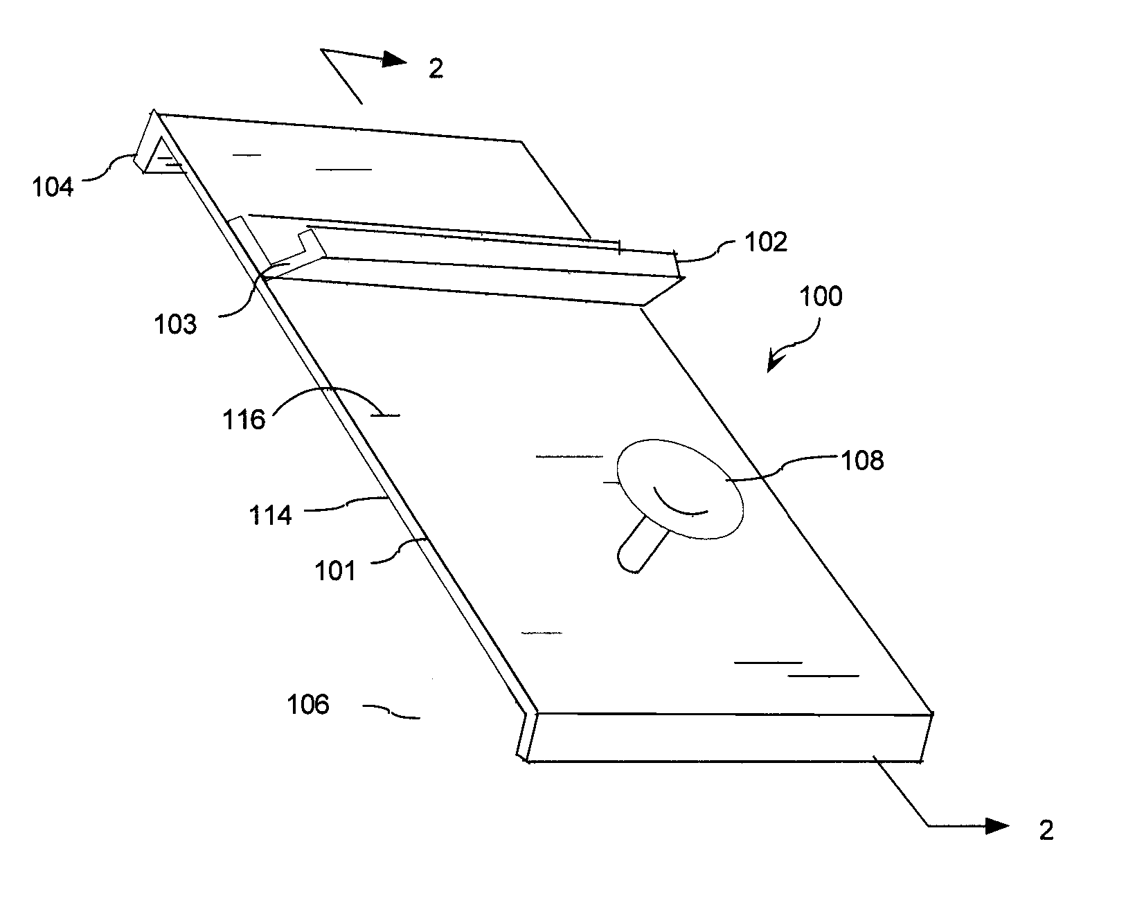
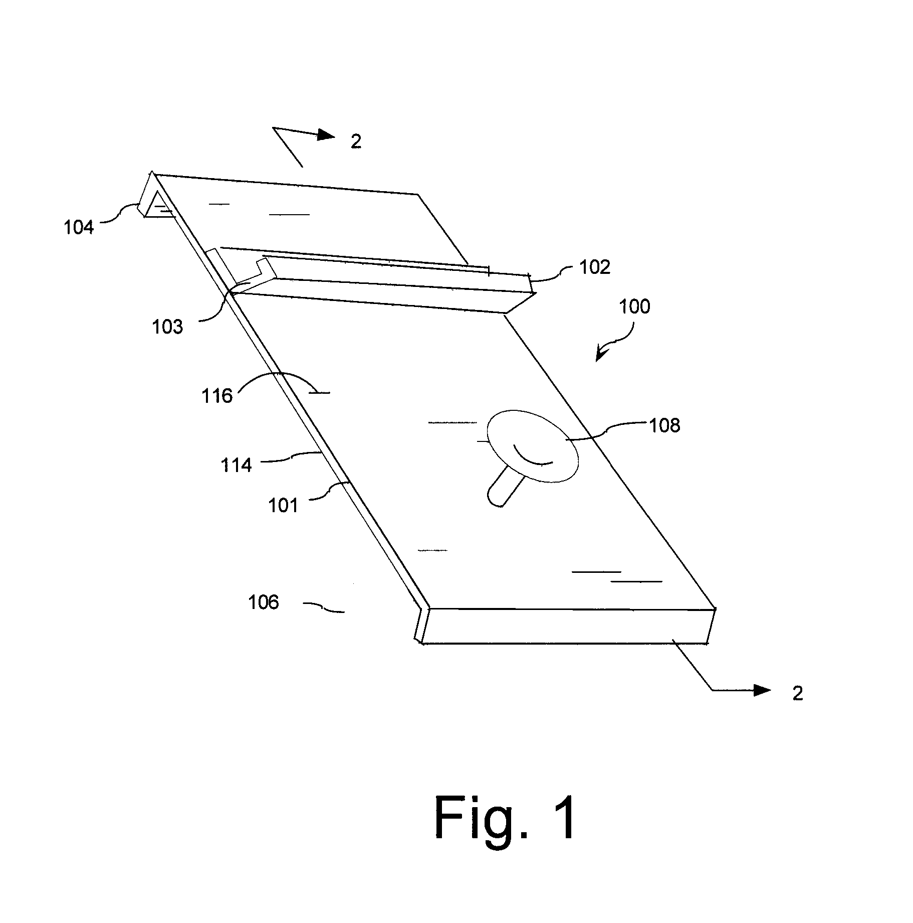
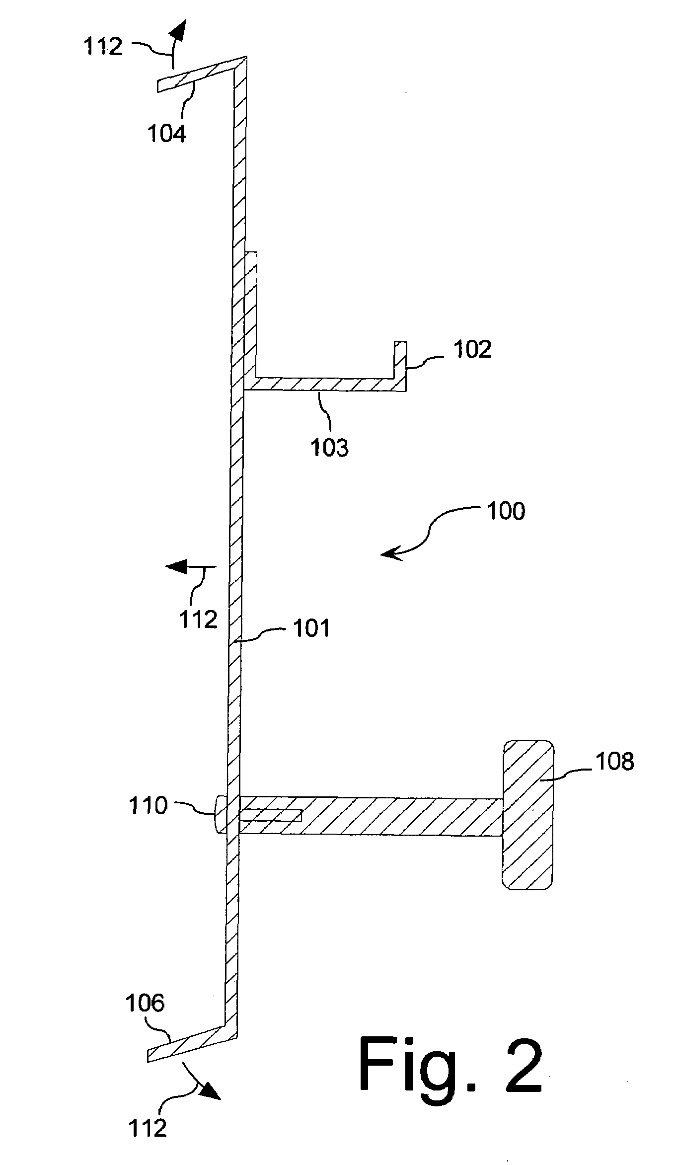
[0016]A tool for efficiently hanging a siding plank on a wall in overlapping relation to a previously attached siding plank is shown in FIG. 1. The tool 100 can include an elongated base member 101. A first lip 104 and a second lip 106 project a predetermined distance from a side 114 of the elongated base member 101 at opposing first and second ends of the elongated base. As best seen in FIG. 2, the first and second lips 104, 106 are advantageously aligned in respective planes that are generally transverse to a plane defined by the elongated base member. Moreover, the first lip 104 and the second lip 106 can be advantageously spaced apart by a distance approximately equal to a width of a plank of siding.

[0017]Referring to FIGS. 1 and 2, a shelf or ledge 102 is also provided on the elongated base member 101. The ledge 102 projects from a second side 116 of the elongated base member 101 opposed from the side 114. As best seen in FIG. 2, the ledge 102 can be aligned in a plane generall...


PUM


Abstract

Tool for efficiently hanging a siding plank on a wall in overlapping relation to a previously attached siding plank. The tool can be secured to a siding plank previously attached to a wall without using a hook that extends behind the previously attached siding plank. These features make the tool more convenient to use and allow the siding job to proceed more quickly. The tool is formed from an elongated base member. A first lip and a second lip project a predetermined distance from the same side of the elongated base member at opposing first and second ends thereof. A shelf or ledge is also provided on the elongated base member.

Description

BACKGROUND OF THE INVENTION[0001]1. Statement of the Technical Field[0002]The inventive arrangements relate to tools for installing siding on a building construction, and more particularly to installing lapped siding.[0003]2. Description of the Related Art[0004]Installation of siding planks for a building construction can be difficult and tedious work. Siding planks are typically installed from the bottom of the structure to the top. Each succeeding planks in typically installed on a wall lapped to a predetermined extent over a previously installed plank. However, it can be difficult to align succeeding planks with the previously installed planks. Further, it can be difficult to ensure that each succeeding plank is properly lapped over previously installed planks. Excessive amounts of overlapping as between adjacent planks can result in excessive numbers of planks being required to completely cover a wall with siding. Insufficient lapping can permit rain and moisture to penetrate th...

Claims


Application Information

Patent Timeline
Patent Type & Authority Patents(United States)
IPC IPC(8): E04D15/00
CPCE04F21/1855
Inventor OUELLETTE, RICHARD D.DEBONO, THOMAS A.
Owner TROPICAL STAR
Why Eureka
Try Eureka