Siding tool

Inactive Publication Date: 2007-03-29
TROPICAL STAR
View PDF36 Cites 13 Cited by
  • Summary
  • Abstract
  • Description
  • Claims
  • Application Information

AI Technical Summary

Benefits of technology

[0010] At least one of the first and second lips can be aligned with a plane that forms an acute angle relative to a plane defined by said elongated base member. For example, the first lip at an upper end of the tool can be angled slightly toward the lower lip to improve the gripping action of the first lip relative to a previously attached siding plank. The second lip on a lower end of the tool can be similarly angled slightly toward the upper lip. Alternatively, the second lip can be angled slightly away from the upper lip to form an obtuse angle with the elongated base member to facilitate attachment and removal of the clip from a previously attached siding plank.
[0011] According to one aspect of t

Problems solved by technology

Installation of siding planks for a building construction can be difficult and tedious work.
However, it can be difficult to align succeeding planks with the previously installed planks.
Further, it can be difficult to ensure that each succeeding plank is properly lapped over previously installed planks.
Excessive amounts of overlapping as between adjacent planks can result in excessive numbers of planks being required to completely cover a wall with siding.
However, all of the currently available tools suffer from one of several limitations.
These limitations relate in each case to the manner in which the tool is positioned while installing each plank

Method used


Image

  • Siding tool
  • Siding tool
  • Siding tool

Examples


Embodiment Construction

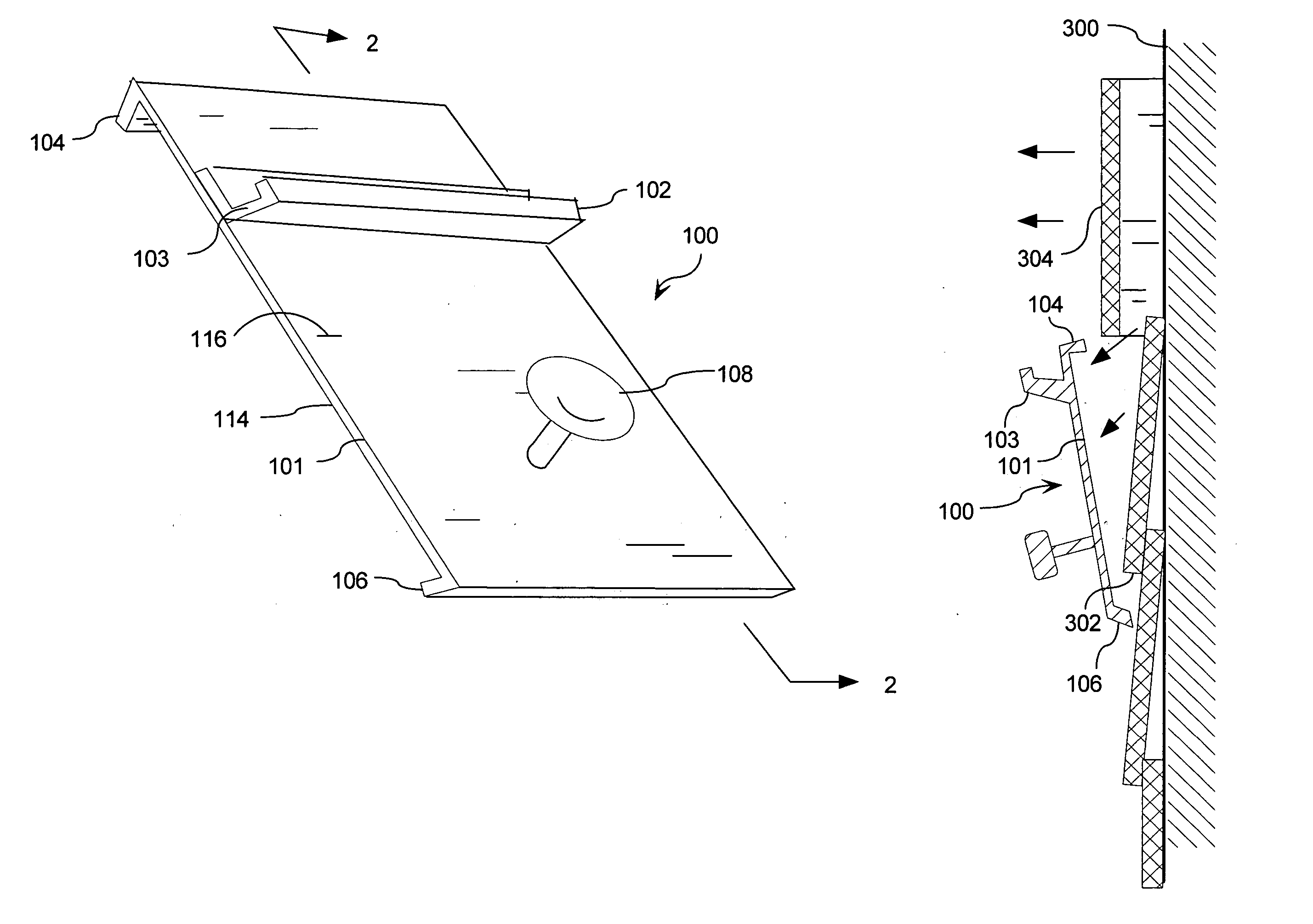
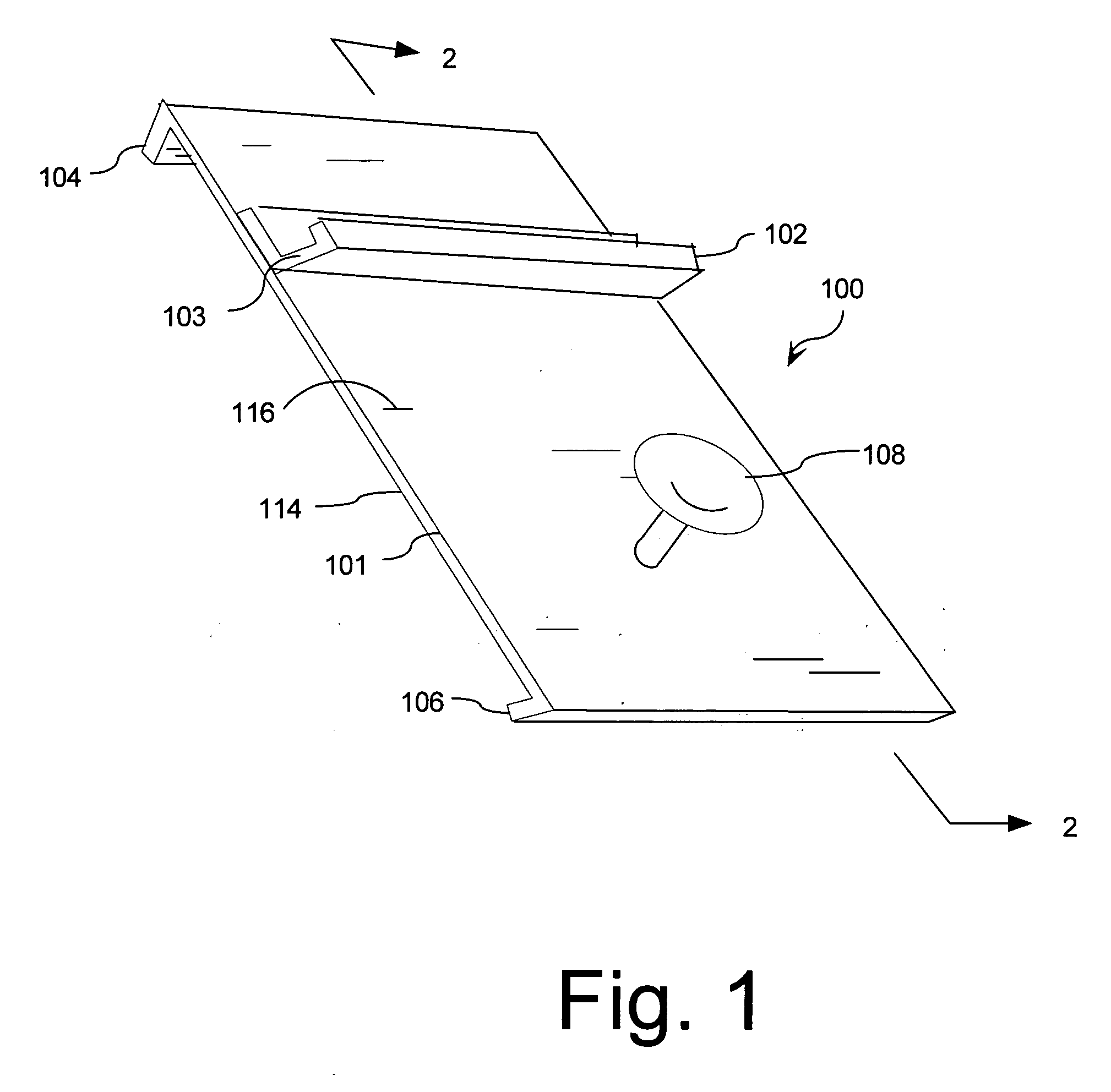
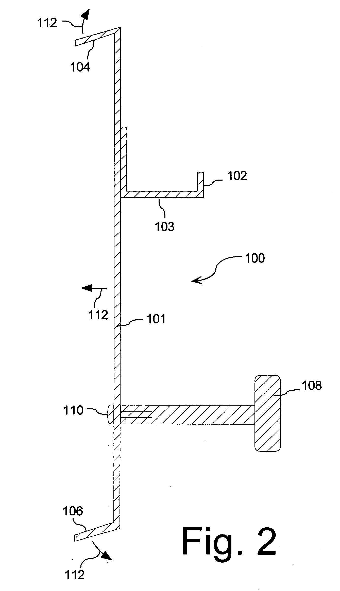
[0016] A tool for efficiently hanging a siding plank on a wall in overlapping relation to a previously attached siding plank is shown in FIG. 1. The tool 100 can include an elongated base member 101. A first lip 104 and a second lip 106 project a predetermined distance from a side 114 of the elongated base member 101 at opposing first and second ends of the elongated base. As best seen in FIG. 2, the first and second lips 104, 106 are advantageously aligned in respective planes that are generally transverse to a plane defined by the elongated base member. Moreover, the first lip 104 and the second lip 106 can be advantageously spaced apart by a distance approximately equal to a width of a plank of siding.

[0017] Referring to FIGS. 1 and 2, a shelf or ledge 102 is also provided on the elongated base member 101. The ledge 102 projects from a second side 116 of the elongated base member 101 opposed from the side 114. As best seen in FIG. 2, the ledge 102 can be aligned in a plane gener...


PUM


Abstract

Tool for efficiently hanging a siding plank on a wall in overlapping relation to a previously attached siding plank. The tool can be secured to a siding plank previously attached to a wall without using a hook that extends behind the previously attached siding plank. These features make the tool more convenient to use and allow the siding job to proceed more quickly. The tool is formed from an elongated base member. A first lip and a second lip project a predetermined distance from the same side of the elongated base member at opposing first and second ends thereof. A shelf or ledge is also provided on the elongated base member.

Description

BACKGROUND OF THE INVENTION [0001] 1. Statement of the Technical Field [0002] The inventive arrangements relate to tools for installing siding on a building construction, and more particularly to installing lapped siding. [0003] 2. Description of the Related Art [0004] Installation of siding planks for a building construction can be difficult and tedious work. Siding planks are typically installed from the bottom of the structure to the top. Each succeeding planks in typically installed on a wall lapped to a predetermined extent over a previously installed plank. However, it can be difficult to align succeeding planks with the previously installed planks. Further, it can be difficult to ensure that each succeeding plank is properly lapped over previously installed planks. Excessive amounts of overlapping as between adjacent planks can result in excessive numbers of planks being required to completely cover a wall with siding. Insufficient lapping can permit rain and moisture to pene...

Claims


Application Information

Patent Timeline
IPC IPC(8): E04D15/00E04F21/00
CPCE04F21/1855
Inventor OUELLETTE, RICHARD D.DEBONO, THOMAS A.
Owner TROPICAL STAR
Why Eureka
Try Eureka