
Pry bar with sliding fulcrum assembly

Active Publication Date: 2012-03-15
SIMTEC
View PDF9 Cites 8 Cited by
  • Summary
  • Abstract
  • Description
  • Claims
  • Application Information

AI Technical Summary

Benefits of technology

[0011]This friction engagement surface may also include a wedged shaped configuration whereby the friction engagement surface frictionally engages the bar with a wedging action in order to further enhance the gripping action between the pry bar and the fulcrum assembly.
[0012]The pry bar and the passage through the fulcrum assembly may have a corresponding non-round cross sectional configuration whereby the fulcrum body is prevented from rotating on the bar.
[0013]An advantage of the combination of the present invention is that the pry bar is provided with a free floating fulcrum assembly which self-adjusts on the pry bar when initially engaging the pry bar with an object to be lifted. It also permits the operator to be positioned closer to the object to be lifted thereby providing effective leverage and maneuverability in tight spaces, and once the lifting force is applied to the bar, there is assurance that the pry bar will not slip relative to the fulcrum assembly.
[0014]The combination pry bar and sliding fulcrum assembly of the present invention provides a free floating fulcrum assembly which will readily self-adjust and positively engage with the pry bar when lifting force is applied. It permits the operator to work closer to the object being lifted, and it also provides a safer lifting mechanism than a pry bar which is provided with a wheeled fulcrum.

Problems solved by technology

An existing problem incurred with the adjustable fulcrum member of this invention is that the pry bar can slide relative to the fulcrum member after the load is engaged with the pry bar, and the fulcrum position therefore cannot be reliably retained and the fulcrum position must be changed by direct hand manipulation of the fulcrum body.
A problem incurred with the slidably mounted fulcrum assembly disclosed in this patent is that the fulcrum assembly must be hand manipulated and engaged and disengaged.
It does not freely slide along the pry bar and therefore is not capable of self-adjustment.

Method used


Image

  • Pry bar with sliding fulcrum assembly
  • Pry bar with sliding fulcrum assembly
  • Pry bar with sliding fulcrum assembly

Examples


Embodiment Construction

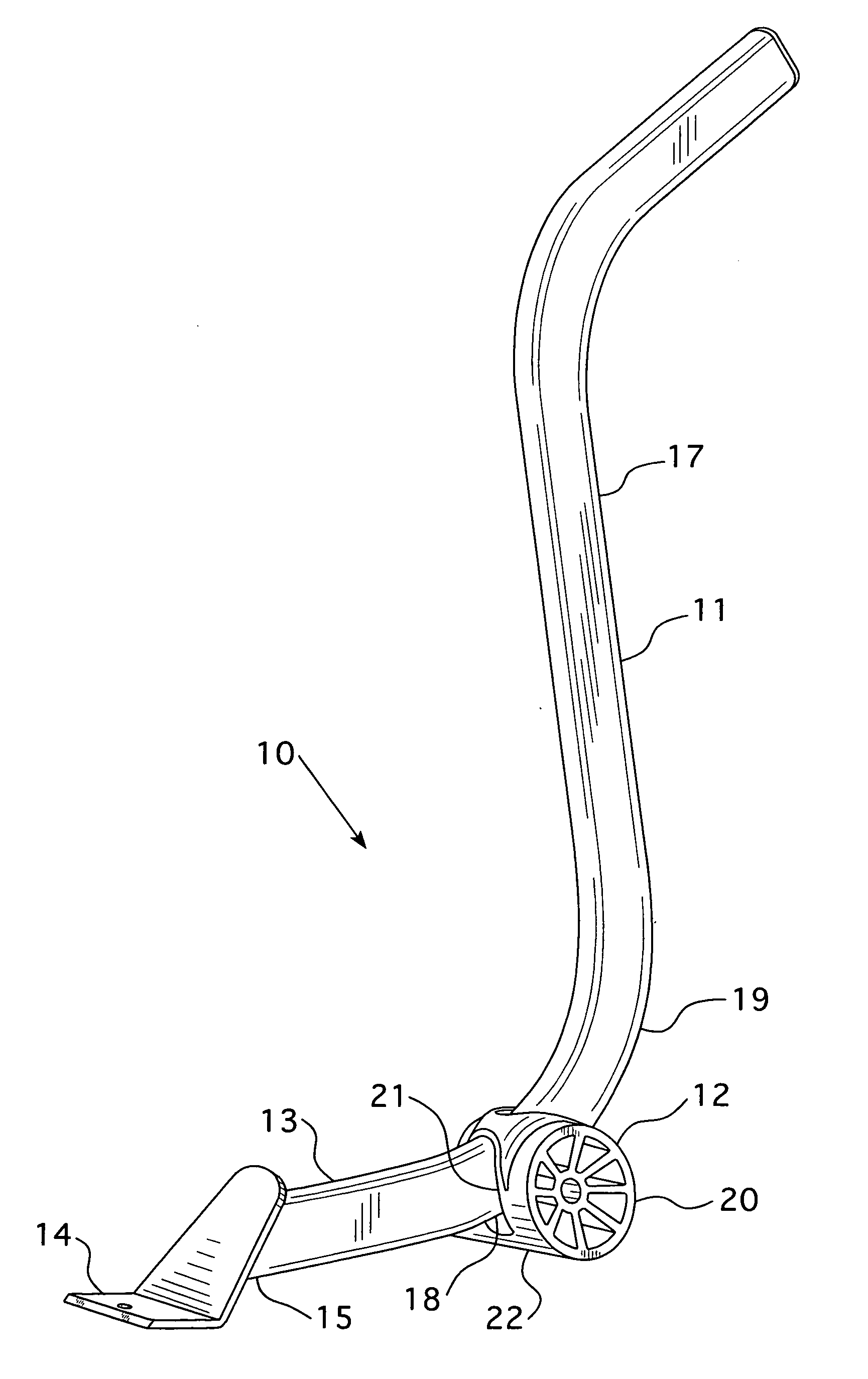
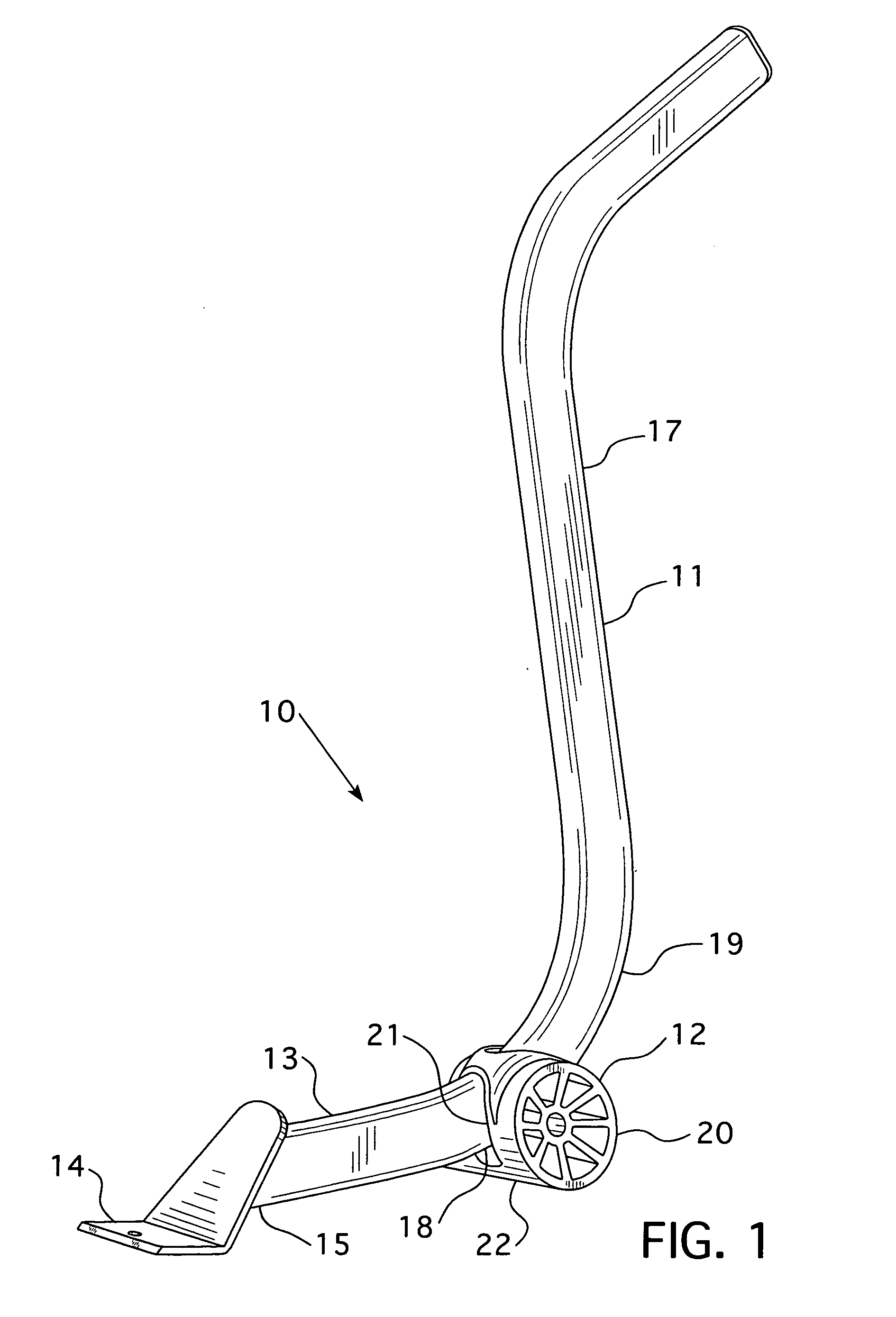
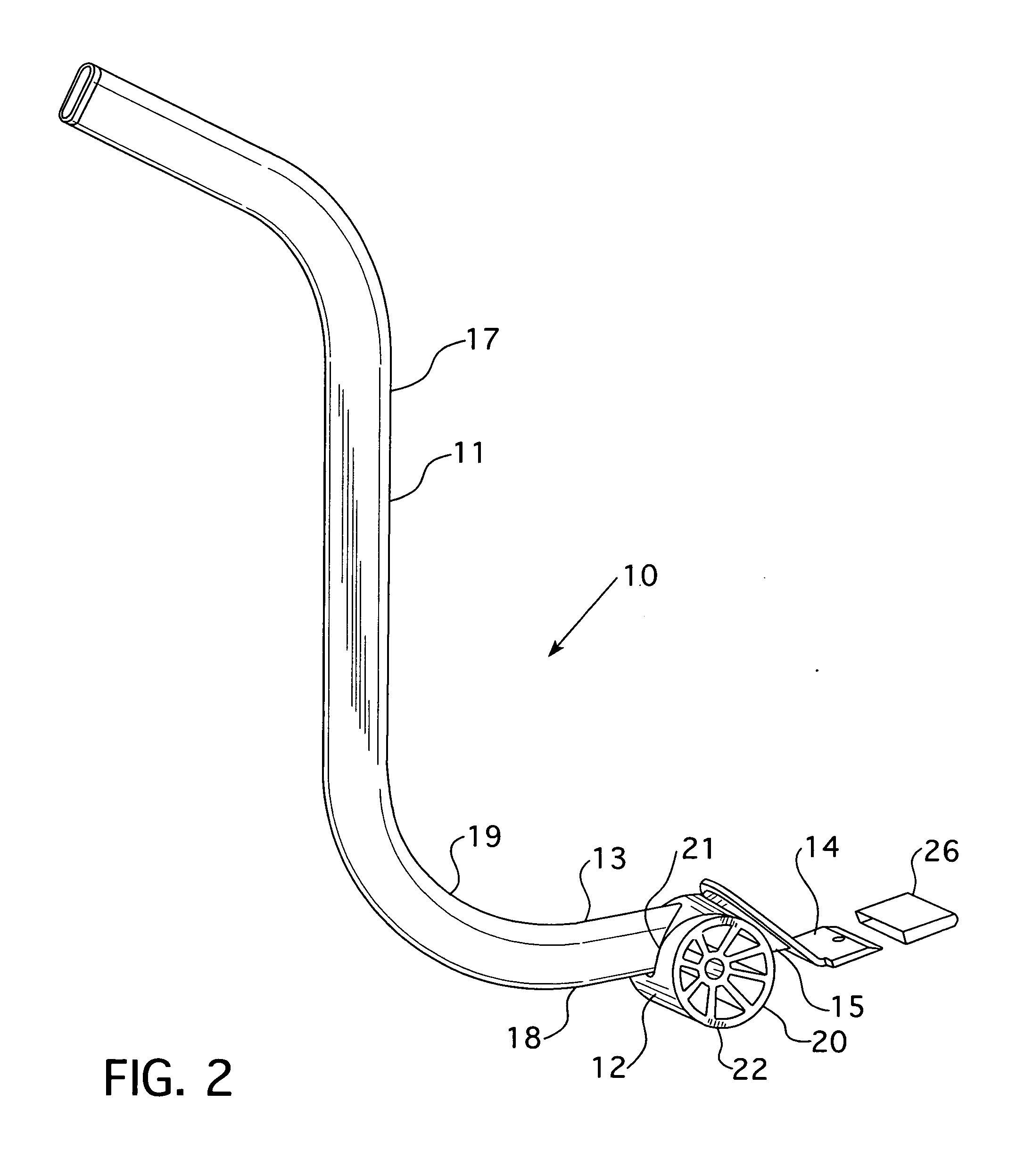
[0022]Referring to the drawings, the combination 10 of the present invention is comprised of pry bar 11 with a sliding fulcrum assembly 12. The pry bar 11 has a generally horizontally extending lifting arm 13 with a lifting lip 14 at its distal end 15 for engaging an object 16a (FIG. 3) or 16b (FIG. 4) to be lifted, and an upright elongated handle 17 coupled to the proximal end 18 of lifting arm 13 through curvature 19.

[0023]Sliding fulcrum assembly 12 consists of body 20 having passage 21 therethrough which is configured and contoured for the body 20 to normally freely slide along bar 11, including curvature 19, when hanging on bar 11. Body 20 is provided with a bottom contact surface having a curvature 22 for engaging a floor surface 23 as a fulcrum for pry bar 11. The axis of this bottom curvature 22 extends transversely to the central axis of extension of elongated pry bar 11.

[0024]The bottom 24 of passage 21 is provided with a bar friction engagement surface 25 at the bottom po...


PUM


Abstract

A pry bar with a sliding fulcrum assembly wherein the sliding fulcrum has a body with a passage therethrough that is configured and contoured for the fulcrum body to normally freely slide along the elongated pry bar, when hanging on the pry bar. The bottom of the passage through the fulcrum body is provided with a bar friction engagement surface on a bottom portion of the passage whereby the fulcrum is non-slidably engaged with the pry bar when the bottom of the fulcrum body is engaged with the floor surface under applied lifting force of the lifting lip of the pry bar applied against an object to be lifted.

Description

CROSS REFERENCE[0001]This application is a continuation-in-part of U.S. Design Patent Application No. 29 / 370,858, filed Sep. 14, 2010, and entitled FURNITURE LIFT.BACKGROUND OF THE INVENTION[0002]The present invention relates generally to a lifting device and more particularly to a pry bar with a fulcrum assembly which is slidably mounted on the pry bar.[0003]Pry bars are commonly used for lifting furniture in the moving industry and in the carpet cleaning industry in order to place a slide under the furniture so that it may be easily moved.[0004]The pry bar of the present invention pertains to pry bars with an adjustable fulcrum which allows a user to obtain the optimum leverage when engaging the object to be lifted with the pry bar lifting end.[0005]Presently there are two such known pry bar assemblies with an adjustable fulcrum member. One is illustrated in U.S. Pat. No. 7,618,020, which discloses an adjustable fulcrum for use with a conventional pry bar. The fulcrum member consi...

Claims


Application Information

Patent Timeline
IPC IPC(8): B66F3/00
CPCB66F15/00
Inventor EDWARDS, DONALD V.
Owner SIMTEC
Learn More